| AutoFEM Analysis Assigning Thicknesses | |||||||
| AutoFEM Analysis Assigning Thicknesses | |||||||
When a finite-element study is created on the base of triangular finite elements (see here) the thickness of each surface part must be defined by the user.
There are several following methods of setting up the thickness of the plate parts.
1) To set up the thickness in the process of study creation:
•Select the object in the list of selected geometry (it will be highlighted in the Preprocessor window). You can select several objects, using Shift and Ctrl.
•Specify the thickness of the selected objects in the field "Thickness of shell entities".
•The button Apply allows us to change the same thickness for all objects with indefinite thickness.
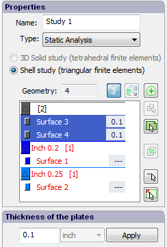
Setting the thickness in the dialogue of study creation
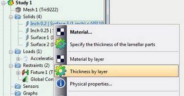
2) The thickness of the shell part can be set up using the study tree from the context menu. For the selection of the group, use Ctrl.
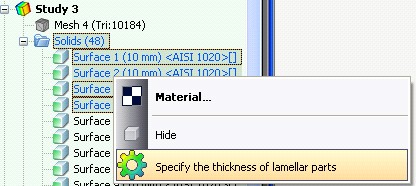
Thickness assignment in the AutoFEM Analysis study tree
3) If the mode of selecting objects in the Preprocessor window is on, it is possible to assign thickness, choosing lamellar parts right in the Preprocessor window and setting up their thickness in the context menu.
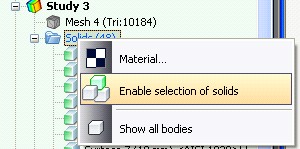
Turning on the mode of selecting objects in the Preprocessor window
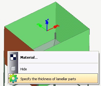
Specifying the thickness in the Preprocessor window (the mode of selecting objects in the Preprocessor window is on)
4) If there are AutoCAD layers in DWG drawing, you can use these layers to assign the equal thickness to all objects which are present on the same layer. To do this, use the contextual menu on the selected body in the Preprocessor window or in the tree of studies and run the command "Thickness by layer". Specified in the next window thickness will be assigned to all parts belonging to the same AutoCAD layer.
See also: Assigning Material, Creating New Material, Creating New Material from Template, Anisotropic Materials, Temperature Curves, S-N Curve, Export / Import of Materials, Getting Materials from ShipConstructor, Physical Properties