| AutoFEM Analysis Creating Finite-Element Mesh | |||||||
| AutoFEM Analysis Creating Finite-Element Mesh | |||||||
Creating the finite-element mesh
For mesh manipulations, use the command:
Command Line: |
FEMAMESH |
Main Menu: |
AutoFEM | Create a Mesh... |
Icon: |
|
The mesh creation command can be automatically called after completing creation of the new study.
A user can manage the mesh generation in order to obtain the mesh of required quality. Generally, an increase in the number of finite elements in the mesh facilitates getting a more reliable result of finite-element modelling. However, with a greater number of elements, requirements to computational resources of the system become firmer. Therefore, it is usually desirable to obtain a compromise mesh which would consist of not very large number of elements, sufficient to get reliable results.Changing approximation parameters, one can generate the mesh of admissible quality.
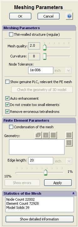
Dialogue of meshing properties |
The Meshing Parameters group contains the following settings. Node Tolerance defines the minimum distance between nodes of mesh when the nodes are treated as separate nodes. If the distance between two nodes is smaller than specified value, these nodes are considered as a single node. Flag Show genuine PLC turns on the regime of the model’s reflection with the good match with the preset parameters of generation of the finite-element mesh. On default, when this flag is removed, the model is reflected in a simplified mode in the Preprocessor that accelerates its visualization. With the regime switched on, the imaging of the model in the Preprocessor window goes on slower, but this regime allows for the use of diagnosis commands to localize errors in cases when the mesh cannot be constructed. Button Check the geometry of 3D model activates the regime of testing the geometry of the 3D model using its current PLC presentation. When possible inaccuracies in the presentation of the 3D model are found, they are shown in the Preprocessor window; also the "Statistics of the Mesh" window shows the number of suspicious objects being found. If these errors do not vanish at the change of mesh construction parameters, the user must analyse the initial AutoCAD 3D model in the fields, marked during the diagnosis process, and correct the 3D model to eliminate the errors. Auto enhancement switches the mode of two-way mesh generation, at which the sizes of finite elements are optimized on the boundaries of narrow internal cavities if they are in the model. Do not create too small elements, if it is checked, prevents creating very small tetrahedral elements to decrease total number of finite elements in mesh.This flag works only for adaptive mesh and regular mesh with quality. It is active by default and recommended for use in the most cases. Remove erroneous tetrahedrons provides removing all erroneous tetrahedrons from the mesh at the end of mesh generation. Due to this, the generated mesh and mesh of calculation fully coincide that makes possible reliable transferring the results from one study to another in the most cases. When this flag is turned off, the erroneous elements are being removed directly before the calculation and the initial mesh and the mesh of the results may differ in this case (if there were erroneous elements). This flag is used by default. |
Flag Condensation of the mesh permits the switching-on of the mode, with which one can set the individual setting of the size of the finite element for separate bodies, facets, and edges of the mesh model.
The process of mesh generation is initiated by pressing button Apply. At that, the command palette is not closed and you can continue to edit mesh parameters.
The Show Errors button is activated if the so-called erroneous objects have been found in the process of mesh generation (usually they are nearly flat tetrahedrons). The erroneous elements are shown in the model by different colours. Pressing the button switches on the mode of edge representation of the finite-element mesh, this shows the locations (in the model) of these elements. The erroneous elements have poor geometric form in terms of finite-element analysis that may affect the results of the strain calculation. However, it is not always possible to avoid them in the finite-element model. In each case, the degree of impact of the erroneous elements on the results must be assessed individually.
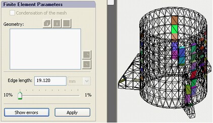
Using the command "Show errors" to display the erroneous elements
Button Show detailed information opens the dialogue showing detailed statistical data on the finite-element mesh. The colour bar graphs allow for the visible assessment of the quality of the mesh constructed in terms of geometric parameters. In total, three bar graphs are available:
Aspect ratio histogram shows the ratio of the maximum side length to the minimum altitude. For a quality mesh, this value should as small as possible. Usually, “thin and flat” tetrahedrons tend to have large aspect ratio.
Face angle histogram shows angles of triangles forming the tetrahedrons’ facets.
Dihedral angle histogram. A dihedral angle is the internal angle at which two adjacent faces of tetrahedron meet by the common edge (the angle between two planes).
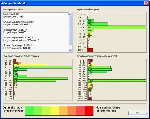
Mesh statistics dialog
Normally, to calculate strains reliably, the shape of tetrahedrons close to equilateral is desirable, i.e. the presence, in the finite-element mesh, of too large (in per cents) number of elements having too small or too big angles is undesired. Whether these elements are present strongly depends on the model geometry. If the 3D model has fillets of a small radius, long and narrow faces or some inaccuracy of performance, probably, it will be impossible to avoid the appearance of “poor” elements. The degree of their influence on the results’ correctness should be assessed individually in each specific case.
After the mesh is successfully created and the work with the command ends (button OK), you can go to setting model materials and imposing boundary conditions.
See also: Purpose and Role of Meshes, Condensation of the Mesh