| AutoFEM Analysis Creating the set of objects | |||||||
| AutoFEM Analysis Creating the set of objects | |||||||
Retrieving the command “Create study” opens a dialogue for creating a set of objects for the purpose of finite-element analysis. If ShipConstructor is loaded and the licence for integration is available, the dialogue for the setups of the system integration opens and allows for the setting of integration setups.
Tuning of integration with ShipConstructor. The mode of integration allows one to obtain the following data:
•Names of the parts set out in SC
•Materials of the parts
•Values of the thickness of laminate parts
•Geometry of specific objects in SC (pipes, hulls).
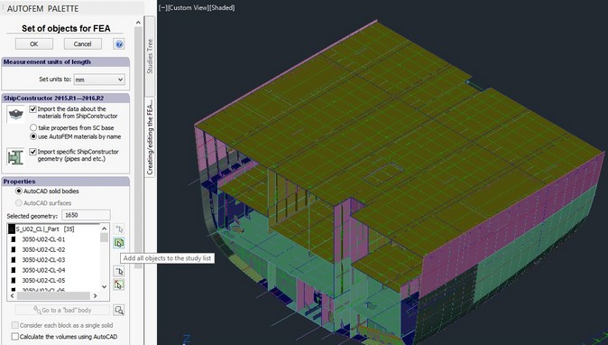
Dialogue for creating the set of objects for FEA with integration setups for AutoFEM and ShipConstructor
Check for overlaps. The first and mandatory stage is the check for the presence of overlaps between 3D solids in the structure. The system does not permit one to create a finite-element mesh if the bodies overlap, because in this case it is impossible to unambiguously define the properties of the material in the overlap area, and the task becomes inexact from the point of physics.
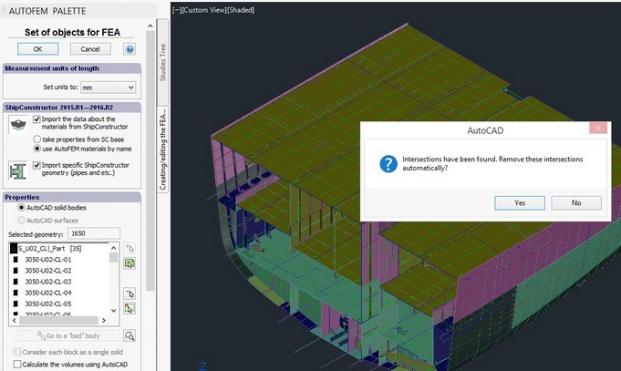
Diagnostics of overlaps
If overlaps are detected, the system offers to resolve the conflicts between the bodies in the automatic mode and withdraws the overlapping zones: it deletes them from one of the bodies following certain algorithms.
Obtaining a 3D model. In the process of acquiring a model with the use of AutoCAD/ShipConstructor, the system updates the user about the current state of the process. If the 3D model embraces high-curvature parts like hulls, the process of obtaining the model may take long time but in most cases, the normal speed is quite fast.
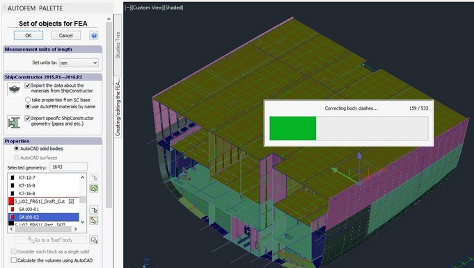
The process of acquiring the model on the basis of AutoCAD/ShipConstructor
Work with “fatal-error” bodies. Sometimes in the course of acquiring geometry from AutoCAD, the system encounters a fatal error when reading this geometry. In this case, the relevant message is displayed, and the fatal-error body is marked in red on the list. The user can enlarge the erroneous body in the AutoCAD window in order to find the reason and eliminate the error in the initial model. For instance, such an error can frequently occur due to full super- imposing of two parts in the space of the AutoCAD model (i.e. the exact duplicate of the part). In this case, in the process of eliminating the overlaps, the solids “destroy each other” and this leads to the error.
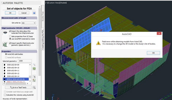
Notification about fatal-error bodies in the course of acquisition of the model in AutoCAD
The user can exclude the erroneous objects from the list in order to make it possible to continue the creation of the set of objects or return to AutoCAD and attempt to correct the geometry.
Diagnostics of the set of objects. If the system reveals any floating parts, the dialogue suggests to open the diagnostics window or go to creating a study will appear at the end of creating the set of objects. The dialogue for the diagnostics of a 3D model allows one to check the geometry of the assembly, downloaded from AutoCAD, and often facilitates the detection and understanding of the reasons, which prevent a mesh creation or proper solution of the finite-element study. For example, the presence of non-fixed parts, which would misrepresent the results as they come to “infinity” under the influence of the applied forces, this is usually prohibited.
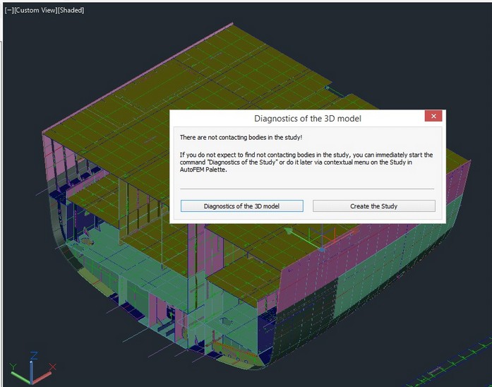
The dialogue for opening the diagnostics of the set of objects
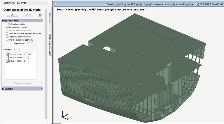
Diagnostics of a set of objects. Option: floating bodies
Next step: Creation of the shell study