| AutoFEM Analysis Creation of the shell study | |||||||
| AutoFEM Analysis Creation of the shell study | |||||||
Upon successful creation of the set of objects for FEA, one can proceed to creating the desirable finite-element study. The study is set out on the basis of the set of bodies for FEA and may include all or selected objects out of this set.
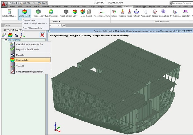
Retrieving the command "Create a study"
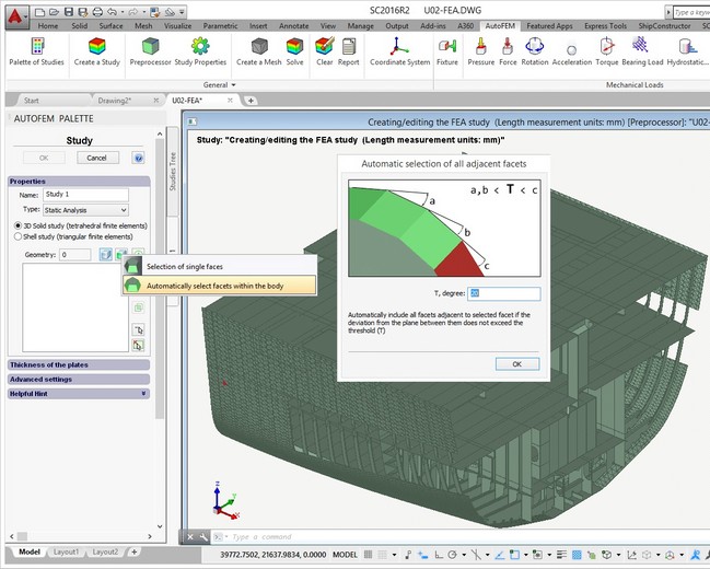
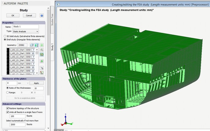
Options of the study creation command. The 3D model of a given vessel unit, obtained from of AutoCAD and ShipConstructor, will have a relatively complex geometry and a great number of parts. It is unreasonable to analyse such a model in a 3D voluminous body, using tetrahedral finite elements, from the point of the computing possibilities; besides, for such a complex model, it is extremely problematic to construct an adequate tetrahedral finite-element mesh. Therefore, considering that the vast majority of the parts of the analysed structure can be deemed as a sheet body, let us select the option “Shell Study”, then the option "Automatically select facets within the body” and set up the permissible angle of the normal deviation for the purpose of automatic facet selection.
Switching on the mode for creating the shell study
Note that additional options for setting up and controlling thicknesses of sheet parts will appear in the dialogue of study creation, as well as options for filtering the objects to be added to the study.
Let us consider the destination of fields in the group Advanced settings.
Option Unite all facets in a single face is designed to optimize the work with hull parts of the ShipConstructor, which often contain several thousand facets, and each facet is seen by AutoCAD as a separate object. With this option selected, all of the numerous subfacets of one solid are integrated in a single face. It provides the opportunity to apply a load to the solid’s face on the whole, regardless of the number of facets properly approximating its geometry. The default threshold value equals 100.
Option Restore topology of the structure (it is used on default) switches on the mode of restoring points of contact between parts when transforming the solid-body model of the structure into its shell equivalent.
The user can choose facets of solids, which, in their opinion, should be included in the study and which would give an approximate picture of the initial structure.
In addition, for holders of a licence for integration with ShipConstructor, the mode of automatic construction of an equivalent shell model is available. Option "Select automatically if not more than ..." allows for the setup of number of facets in the body, surpassing which the system will not add this body to the study automatically. Usually it concerns hulls, for it is more efficient to select these objects manually.
Automatic development of the model. For automatic construction of the shell model, press the button Add all objects to the study list. The system analyses the geometry of the structure according to the algorithm described above and creates an equivalent estimate model based on the faces of plate parts. The system automatically defines and assigns values of the thickness of plate parts. If when creating the set of objects for FEA, we have used the mode of integration and the thickness of the plate part has been set up in SC, then the user’s value in SC applies. If the thickness of the plate part was not set in SC or the integration mode was not used, the system would calculate this value automatically. To control the accuracy of the assignment of thickness values, special tools are used, which allows one to locate “suspicious” thickness values among the parts.
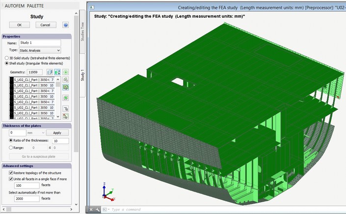
The field Ratio of thicknesses sets up the permissible ratio of thickness values among all parts of the model. If this value is exceeded, the parts with thickness values which do not meet the said criterion will be shown in red on the list. It is recommended that the known spread of thickness values should be estimated in advance, so that one will be able to detect objects with erroneously assigned thicknesses, if any. For instance, we know that for our structure, plate materials are used in a thickness range of 5 - 14 mm. If the system detects a thickness value of 1 mm for a part, this part will be highlighted on the list; also, the button Go to a suspicious plate will be available.
The tool Range allows one to highlight all parts with thickness values out of the range set by the user in the list.-
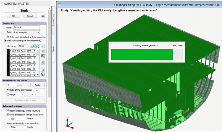
Automatic construction of an equivalent shell estimate model using the initial 3D solid-body geometry
Manual selection of hulls. Parts of a hull can be conveniently and efficiently put into the study in manual mode. To do this, one must left click the mouse at the inner surface of the part of interest at any area of a facet. The system automatically adds all other areas of this facet to the study. Sequentially choosing internal facets of all hulls, will facilitate the completion of the set of data for the study.
Adding hull parts in the study
Editing the model. One advantage of the approach used in AutoFEM Analysis is the possibility of interactive editing of the estimated shell model by the user. At any stage of the model construction, the user may interfere in the process to obtain a more adequate version of the estimated model. A repeated click of the left button on the mouse on the facet selected will lead to its exclusion from the study. The user can always redefine the facet, selected in the automatic mode, also specifying a more fitting one in this instance.
All necessary elements of the model are put into the study
Next step: Construction of a finite-element mesh
