| AutoFEM Analysis Example of Interpreting Result | |||||||
| AutoFEM Analysis Example of Interpreting Result | |||||||
In this paragraph, we will provide an example of detailed result interpretation for a specific structural study, and then take all necessary measures to fix the model's flaws.
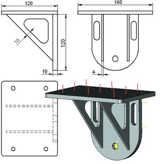
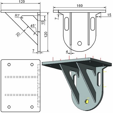
The original model is a mounting part, whose drawing is shown below. The mounting is loaded with the force of 3500 kilograms, evenly distributed over the horizontal plate. The model material is steel. There are two restraints: a full restraint at the bottom hole, and a partial restraint with the ban on longitudinal axial displacements – for the vertical plate.
The main criterion for assessing the structural strength is the Factor of safety (FS), as we mentioned earlier. The minimum FS value for this part should be no less than 1.5. After getting first results, one can see the general picture of the factor distribution, shown on the colour diagram at the right.
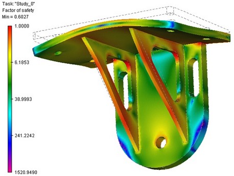
In this case, we are interested in the zones, in which the FS approaches critical values. We can scan the model using the mouse and pointing it at the places of interest, getting the result in the pop-up tooltip. However, for better visual representation of such zones, let's set up the colour scheme as shown on the next figure.
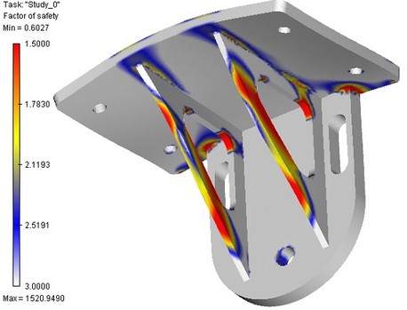
We specify the range of values of interest from 1.5 to 3. For convenience, we will correct colour assignments. Anything greater than 3 will be displayed White – we are not interested in those zones for the time being. The critical zones with the value below 1.5 will be Red. The rest of the values in the range will be assigned a colour according to the colour scale settings.
In this way of displaying the result, one can instantly notice the places of the model that require fortification. We also see from the scale, that the minimum FS value is 0.6, which is not admissible.
We then proceed with fixing model flaws. First of all, let's strengthen the pillars by increasing the cross-section area, and the area of the vertical and horizontal plates connection. Also, when analysing the general picture of factor of safety distribution, one can discover zones of excessive strength. This allows saving material. Thus, it is possible to reduce the thickness of the vertical plate and eliminate rigidity ribs on it. The new mounting drawing is shown below.
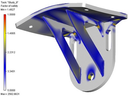
After updating the mesh and running calculations the second time, we can see that the factor of safety no longer reaches critical values in the «problematic» zones.
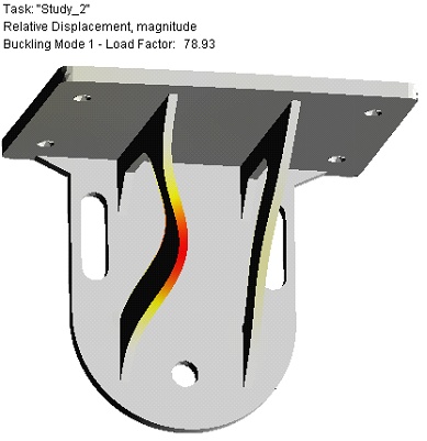
To state the final conclusion about the strength of the mounting, we must run the buckling analysis of the part. Such an analysis indicates that the critical safety factor for the mode 1 and this type of loading is 79, which means a sufficient margin of structural strength against buckling.