| AutoFEM Analysis Bearing Load | |||||||
| AutoFEM Analysis Bearing Load | |||||||
To specify Bearing load, use one of the following methods:
Command Line: |
FEMABLOAD |
Main Menu: |
AutoFEM | Loads/Restraints | Bearing load |
Icon: |
|
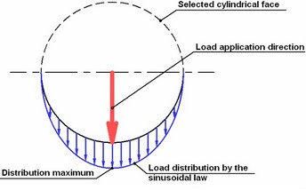
Bearing load simulates the load occurring under a direct impact of such parts as an axle, a bearing or a shaft. A cylindrical face is used as the location for applying the load. The applied force is distributed according to the sinusoidal law (see the diagram).
After invoking this command, it is required to select elements (faces) of the model for applying the load:
The selected element will be added to the list.
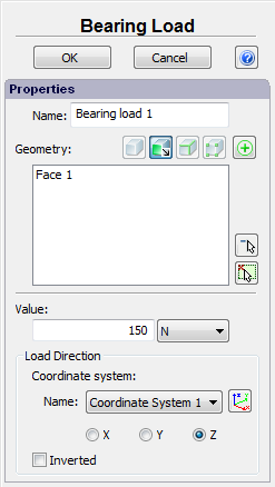
It is necessary to specify:
•the magnitude of load;
•units: N, kgf, lbf;
•load direction
in the properties window.
Load direction. The user can select an axis (X,Y or Z) of the local coordinate system (if the local coordinate system is not specified, the global coordinate system will be used by default) as a direction of acceleration.
To import the existing local coordinate system, use one of the following ways:
Command Line: |
FEMALCS |
Main Menu: |
AutoFEM | Reference Geometry | Coordinate System |
Icon: |
|
The user can tick the option "Inverted" to reverse the load direction.
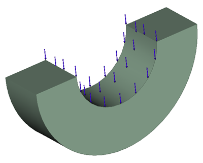
In the 3D scene Bearing load is shown in the following way:
A typical sequence of step for specifying Bearing load:
1.Initialize the command "Bearing load" ![]() .
.
2.Select a cylindrical face or a set of faces.
3.Specify the units and magnitude of load.
4.Specify the load direction.
5.Complete the command.
See also: Mechanical Loads, Force, Pressure, Hydrostatic Pressure, Centrifugal Force, Gravity, Acceleration, Bearing Load, Torque, Torque at Nodes, Additional Mass, Remote Force, Remote Moment, Remote Mass