| AutoFEM Analysis Contact | |||||||
| AutoFEM Analysis Contact | |||||||
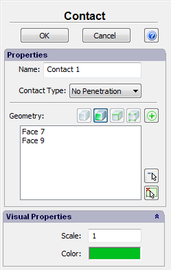
To define a contact, use the command:
Command Line: |
FEMACONTACT |
Main Menu: |
AutoFEM | Loads/Restraints | Contact |
Icon: |
|
Contact restraints are needed in studies of contacting bodies.
To define a contact, you need to select the contacting faces of two bodies. Next, select one of four contact types:
•bonded;
•free (no contact);
•no penetration;
•virtual wall.
The contact type Bonded is used in the case when it is necessary to bond the contacting surfaces of the bodies. The bodies are considered as bonded in this case, so that relocations of a face in one body result in relocations of the other body faces without any restrictions. If the bodies are made of materials with different physical characteristics, then the finite element model correctly accounts for the different material properties of different faces of contacting bodies.
If the contact area is not subjected to any restraints, then use the Free type. In this case, the contacting surfaces can freely move with respect to each other. Therefore, when using this contact, one should be on guard against mutual penetration of contacting faces when a load is applied.
The No penetration contact differs from Free contact in that it bans mutual penetration of the contacting faces. This contact type allows modelling such physical phenomena as sliding of one body along another one, occurrence of gaps at the part connection locations due to deformation, etc. We would like to also note that using the No penetration contact implies existence of a physical contact between body faces in the initial state of the structure being analysed.
Virtual wall is an imaginary firm object through which cannot penetrate contacting face of the model. Virtual wall is used to model a contact of a body with a rigid surface, whose deformation can be neglected for the modelling purposes. In this case, all that is necessary is to define the faces of the first body that contact the Virtual wall. It is implied that contacting with "Virtual wall" faces of the model can slip on their plane.
It is possible to set default contacts.
Command Line: |
FEMADEFCONT |
Main Menu: |
AutoFEM | Loads/Restraints | Set default contact type |
Icon: |
|
This command defines the contact type to use by default. This serves to define global contact parameters for all bodies in contact. For example, if a combined structure is being calculated, that consists of several rigidly connected parts, then defining the default contact as "bonded" helps avoid manual definition of the contact type for all surfaces in contact. Default contact parameters can be redefined with the help of the «Contact» command.
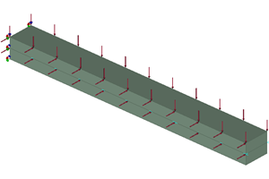
The dependency of a model behaviour on various contact types can be illustrated with the following example. Two beams are kept together using a contact restraint, with one end fixed, and a distributed force acting normal on the top and side surfaces of the first beam.
|
Initial Model |
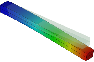
If the "bonded" contact type is used, then the combined beam is deformed as a single solid.
|
Contact type «bonded» |
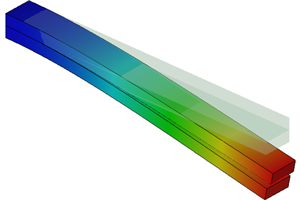
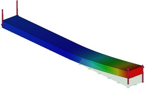
In the case when the "no penetration" contact is used, one can see that the top beam makes the lower one deformed and at the same time slides along it.
|
Contact type «no penetration» |
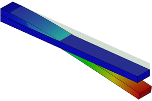
When using the "free" contact, one can observe penetration of the top beam into the lower one, which shall be avoided when designing assembly models.
|
Contact type «free» |
|
Contact type «Virtual wall» |
A typical order of steps for defining the contact restraints is as follows:
1. Initiate the «Contact» command ![]() .
.
2. Select contacting faces of the first body.
3. Select contacting faces of the second body.
4. Define the contact type.
5. Complete the command.
See also: Fixture.