| AutoFEM Analysis Force | |||||||
| AutoFEM Analysis Force | |||||||
To specify the load Force, use one of the following methods:
Command Line: |
FEMAFORCE |
Main Menu: |
AutoFEM | Loads/Restraints | Force |
Icon: |
|
Force is a type of loading used to specify a concentrated load, and also for specifying a total magnitude of distributed load.
After calling the command, select the model elements for applying the load. Use one of the following menu options:
|
|
|
|
|
Loads/Restraints on vertices |
|
Turns on the selector in the mode “adding-only” |
|
Select all entities of the chosen type which are located in the same plane |
Select faces, edges or vertices of the model being analysed. The selected objects are added to the list.
You also need to define the numeric value, units and the load direction in the properties window of the Force.
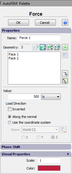
Numeric value. The numeric value is defined as a total equivalent magnitude of uniformly distributed along the edge length (over the face area) load.
When the Force is uniformly distributed, the load per unit length of the edge (per unit area of the face) is equal to the ratio of the specified load magnitude to the edge length (face area).
It is worth noting that if the load magnitude is specified simultaneously for several elements (it is allowed to select the elements of a single type only: vertices, edges or faces), its total value will be distributed between them in the following way:
•The load magnitude equal to the ratio of the specified load to the total area of the faces will be acting on a unit area of each face;
•The magnitude equal to the ratio of the specified load to the total length of edges will be acting on a unit length of each edge;
•Each vertex will be subjected to the part of the force equal to 1/n, where n- is the number of vertices.
Units. For the load Force the following units can be used: N, lbf, kgf.
Load direction. The user can select the normal to the loaded face or an axis (X, Y or Z) of the selected local coordinate system (if the local coordinate system is not specified, the global coordinate system will be used by default) as a load direction.
To import the existing local coordinate system, use one of the following ways:
Command Line: |
FEMALCS |
Main Menu: |
AutoFEM | Reference Geometry | Coordinate System |
Icon: |
|
The user can tick the option "Inverted" to reverse the load direction.
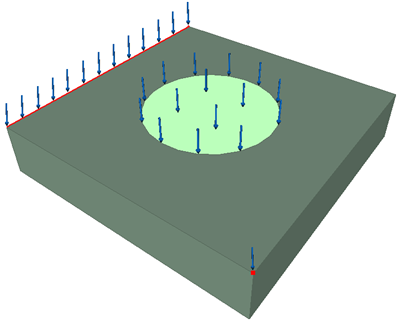
The load Force is shown by arrows in the 3D- scene. The arrows show the direction of the load.
The distributed load sometimes has to be applied only to a certain part of the edge or face,corresponding to the domain of action of the external load, and not to the entire face or edge of the model. To apply the load to the part of the face, first the geometry of the desired shape must be created on the face, and then the command " Modify | Solid Editing | Imprint Edges " should be used. |
Typical sequence of steps for specifying the load Force:
1.Initiate command "Force" ![]() .
.
2.Select a face, an edge, a vertex, a node or a sequence of elements.
3.Specify the units.
4.Specify the load magnitude.
5.Specify the direction of load action.
6.Complete the command.
See also: Mechanical Loads, Force, Pressure, Hydrostatic Pressure, Centrifugal Force, Gravity, Acceleration, Bearing Load, Torque, Torque at Nodes, Additional Mass, Remote Force, Remote Moment, Remote Mass