| AutoFEM Analysis User Coordinate System | |||||||
| AutoFEM Analysis User Coordinate System | |||||||
User Coordinate System
User systems of coordinate are often used to define the direction of loads, acceleration, rotational axis and etc. There are several ways to create the user coordinate system in AutoFEM. The first approach is based on importing the named user coordinate system from AutoCAD. This coordinate system must have the name in AutoCAD. The second way allows to create the coordinate system based directly on elements of the 3D model in the Preprocessor window. To open the dialog of the command "Coordinate System", use the button in the AutoFEM Ribbon or inside the AutoFEM Palette.
Command Line: |
FEMALCS |
Main Menu: |
AutoFEM | Reference Geometry | Coordinate System |
Icon: |
|
1. Import of Named Coordinate system from AutoCAD. For using the user coordinate system (created into AutoCAD) to apply restraints or loads you need to import this coordinate system. Select one of the introduced coordinate systems from the list and press the button ![]() . New coordinate system will be created at the same point of space as AutoCAD UCS.
. New coordinate system will be created at the same point of space as AutoCAD UCS.
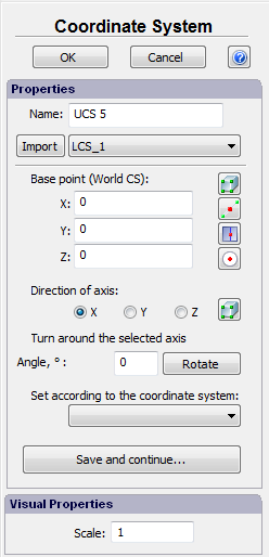
2. Creating the coordinate system based on absolute coordinates or 3D model geometry. Use X, Y, Z coordinates to define the origin point of the coordinate system in the world coordinate system or select an entity of 3D model geometry. A special selector allows the user to turn on the mode of object selection to facilitate defining the position of the coordinate system. Following selector options are available.
|
Selection of 3D model vertexes to set the origin of coordinate system or the direction of the axis |
|
Selection of the middle between two selected points (vertexes) |
|
Selection of the middle of a straight edge |
|
Selection of the center of a circular edge |
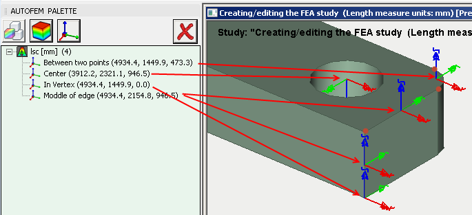
Use of different selection modes to define the origin of UCS
After defining the center of the user coordinate system, it is possible to set the directions of the axes using 3D model vertexes or specifying a rotation angle. Also the user can adjust the created coordinate system according to existing one (so, that their axes will coincide). Parameter "Scale" defines the size of CS sign.
The typical procedure for setting the user coordinate system is as follows:
| 1. | Initiate the command ”Coordinate System” |
| 2. | Define point of origin of the coordinate system selecting the vertex of 3D model or specifying X,Y, Z coordinates. |
| 3. | Specify the desirable direction of the axes of coordinate system. |
| 4. | Click "Save and continue..." to save the current coordinate system and proceed the next coordinate system creation. |
| 5. | Pressing OK, complete the command. |