| AutoFEM Analysis Generating Reports | |||||||
| AutoFEM Analysis Generating Reports | |||||||
The user can create electronic documents containing basic information about a calculated study, which are independent of AutoFEM. Reports are generated in the html format, so that viewing them is possible in any browser, for example, MS Internet Explorer or MS Word. To create a report of the active study, use the command:
Command Line: |
FEMAREPORT |
Main Menu: |
AutoFEM | Create Report... |
Icon: |
|
The report settings dialogue can also be accessed from the context menu by right clicking ![]() on the name of the selected study, via the command «Report…».
on the name of the selected study, via the command «Report…».
A report contains basic information about the model, materials, and the computational finite element mesh, as well as coloured result diagrams, which are displayed in the studies tree or opened in the calculation results view windows at the moment.
In addition, a 3D model of the result can be saved in format .vrml while saving all colour information about the result. To view the result in 3D, one should use the off-site plugin, for example,Cortona3D (www.cortona3d.com).
Let's review the main controls of the report generation dialogue.
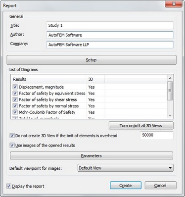
«General» group contains information on the name of the study, for which the report is being generated («Title»), information about the report creator («Author» - by default, the information is accessed from the document properties), and company information, which is also accessed from the document properties by default.
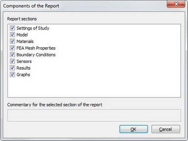
The button «Setup» shows the dialogue to select the sections of the report to generate and supply a commentary concerning each report section.
«List of Diagrams» lets the user to check-mark the result types, whose graphical images will be added to the generated report. The click of mouse inside the columns 3D of the table switches the mode of saving 3D model of the result (Yes/No). Buttons below the list allow to show/hide all 3D images of the selected type.
Flag «Do not create VRML...» allows to set the number of finite elements when the VRML 3D model will not be created. The necessity to set this limit is caused by obstacle that creating the VRML 3D model of the large finite-element model may take significant time and is not justified in this case.
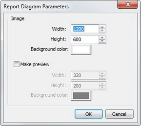
A button [Parameters] is provided next to the list of diagrams, which you can use for calling the dialogue for defining diagram display parameters. Here you can specify the picture size in pixels, and the background colour. You can also enable creation of preview and set up its image. In this way, the main report document would include reduced-size images of result diagrams, with the full-size images being accessible by clicking ![]() on the small image, when viewing the report file, for example, in the Internet Explorer.
on the small image, when viewing the report file, for example, in the Internet Explorer.
«Use image of opened results» allows adding to the report the currently opened diagrams in their current orientation, the way they appear in the calculation results window. If there are no open result windows, or the control is not active, then the diagrams are added to the report in the default orientation («axonometric front»).
Clicking the button [Create] brings up the dialogue for saving the report file. By default, the report is saved in the current folder of the model file and uses the name in the format «model_file name_study name».html.
When generating a report, a folder with the same name is created to store the files of graphic result images in the .png format. Keep in mind this fact when porting a report to another work seat or when passing to a third party.