| AutoFEM Analysis Mathematical Background of AutoFEM | |||||||
| AutoFEM Analysis Mathematical Background of AutoFEM | |||||||
Engineering design often requires investigation of the most important physical and mechanical properties of parts, assemblies, or the entire product. For example, in a design one must evaluate the strength of parts under specified loads or maximum deformations of a product's body. For a long time, the only means for evaluating physical and mechanical properties of products was assessment based on approximate analytical or semiempirical methods, listed in industry guides. The accuracy of such methods is generally not high, with respect to real-life design objects. Consequently, significant «safety factors» (as with respect to the strength) are incorporated, in order to lower the risks of an unviable design.
Emergence of computers and development of computer science led to big changes in traditional approaches to engineering calculations. From the mid-60s of the 20th century, the leading method of numerical solving a wide variety of physical problems became finite element method (FEM). The special features of the FEM that put it in the commanding position in the applied computational mathematics are such inherent qualities as:
•versatility – the method is suitable for solving all kinds of different problems of mathematical physics (mechanics of deformable solids, heat transfer, electrodynamics);
•good algorithmization – the suitability for developing software suites that cover a wide scope of applications;
•good numerical stability of FEM algorithms.
Emergence of personal computers and their increasingly wide use for design purposes impacted the accelerated development and availability of finite element analysis application systems that do not require the user to be deeply proficient in FEM theory, eliminate labor-intensive operations of manual preparation of initial data and offer excellent opportunities of processing results of mathematical modelling.
AutoFEM belongs to modern finite element analysis systems, oriented at a wide range of users, who, by the nature of their responsibilities, face the requirement of assessing product behaviour under conditions of various physical influences. AutoFEM is oriented at a nonspecialist in the area of finite element analysis and does not require the user to have in-depth knowledge in the area of mathematical modelling for effective use of the system. Nevertheless, correctness of results of a mathematical modelling and their appropriate assessment are determined to a significant degree by the user's proficient approach to formulating physical problems, which are to be solved with the help of AutoFEM.
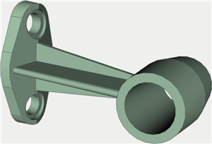
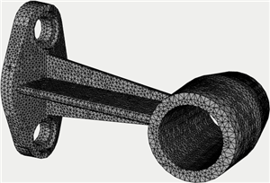
The centre point of the finite element method is in replacing the original spatial structure of a complex shape by a discretized mathematical model that appropriately represents the physical essence and properties of the original product. The most important element in this model is the product's finite element discretization - which implies building a set of elementary volumes of the specified shape (the so-called finite elements, FE), combined in a united system (the so-called finite element mesh).
AutoFEM is oriented at solving physical problems in spatial formulation. The product's mathematical approximation uses its equivalent replacement by a mesh of tetrahedral elements. A tetrahedral finite element is convenient for automatic generation of the computational mesh, since the use of tetrahedra permits a high-accuracy approximation of a however complicated product shape.
|
|
Original structure and its finite element discretization |
|
The structure that itself represents a distributed system of a complex geometrical shape is represented as a union of finite elements. The finite elements that approximate the original structure are considered connected to each other at the corner points - the nodes, in each of which the three translational degrees of freedom are introduced (for mechanical problems). The external loads applied to the structure are converted to equivalent forces applied to the nodes of finite elements. Restraints on the structure's motion (fixings) are also transferred to finite elements that model the original object. Since the shape of each FE is defined in advance, and its geometrical characteristics are known, as well as the material properties, therefore a system of linear algebraic equations (SLAE) can be written out for each FE that is used for modelling the structure, describing displacements of FE nodes under the influence of forces applied at these nodes.
By writing out a system of equations for each finite element that is involved in approximating the original physical system, we study those together and get a system of equations for the entire structure. The order of this system of equations is equal to the product of the number of movable nodes in the structure and the number of degrees of freedom introduced in one node. In AutoFEM, this usually amounts to tens or hundreds thousand algebraic equations.
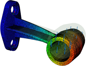
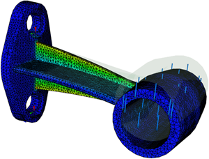
By building the system of equations for the entire structure and solving it, we get the values of the sought physical measure (for example, displacements) in the nodes of a finite element mesh, as well as additional physical measures, for example, stresses. Those values will be approximate (with respect to the theoretically possible «exact» solution of the respective differential equation of mathematical physics), however with the miscalculation error being possibly very small – fractions of a percent on test problems having «exact» analytical solution. The error of the solution obtained as the result of a finite element approximation is usually decreasing smoothly with the increased degree of elaboration on the modelled system discretization. In other words, the greater is the number of FE involved in a discretization (or the smaller are the relative dimensions of a FE), the more accurate is the resulting solution. Naturally, a more dense subdivision of FE demands more computational power.
|
|
Results of finite element modelling (displacements and stresses) |
|
The described algorithm of finite element modelling is applicable for solving various problems, which a modern engineer may encounter – heat transfer, electrodynamics, etc. Due to advantages accounted for above, FEM became the leading method of computer modelling of physical problems and, in fact, associates with a whole branch of the modern IT industry, known by the acronym CAE (Computer Aided Engineering).