| AutoFEM Analysis Plane of Symmetry | |||||||
| AutoFEM Analysis Plane of Symmetry | |||||||
This command allows to define symmetry planes for a physical system, i.e. the planes relative to which the structure’s deformation is supposed to be symmetrical. As a rule, the symmetry planes are used to decrease the dimensionality of a problem being solved, at the expense of the possibility of analysing only one part of the structure. At that, the significant (at least by 2 times) reduction in the number of algebraic equations (at the same level of discretization) is achieved.
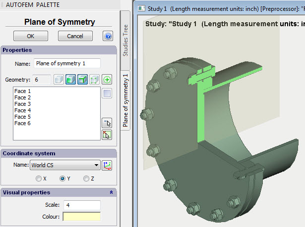
Dialogue of the command “Plane of symmetry”
To use the command, you should to prepare in advance the 3D model, corresponding to that part of the structure which is obtained from the whole structure by cutting by one or more mirror planes. Besides, if the symmetry plane does not coincide with the planes of the global system of coordinates, you should create the local system of coordinates for each mirror plane; one of the axes of that coordinate system will set the normal to the mirror plane.
One command may preset only one plane of symmetry. All selected objects must be located in the same plane of symmetry.
The procedure of working with the command is as follows.
1. Initiate the command “Plane of symmetry”.
Command Line: |
FEMASYMMETRY |
Conrextual Menu: |
AutoFEM | Restraints | Plane of Symmetry |
Icon: |
|
2. Select model elements (facets and/or ribs), which lay in the symmetry plane.
3. Select the system of coordinates and the coordinate axis, defining the normal to the symmetry plane.
4.Complete the command.
See also: Using Symmetry, Symmetry of 3D structures, Symmetry of shell structures