| AutoFEM Analysis Torque at Nodes | |||||||
| AutoFEM Analysis Torque at Nodes | |||||||
This type of load is used to specify torque to nodes and edges of finite element model based on triangular elements.
To specify Torque at nodes, use one of the following methods:
Command Line: |
FEMANODEMOMENT |
Contextual Menu: |
Torque at nodes |
Icon: |
|
You can use edges and nodes as the location of the load application. To select edges or nodes, use the next options:
|
|
|
Select only nodes (vertex of model) |
Selected objects are entered in the list.
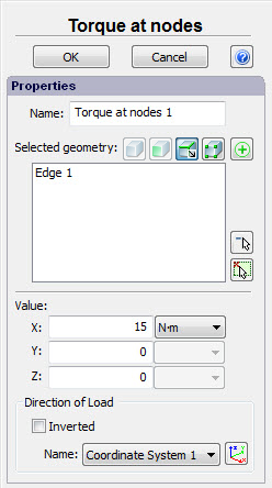
It is necessary to specify:
•the summary magnitude of load. Specified value of torque is uniformly distributed on all selected elements of the model. If three nodes were selected, the value of torque at each node is equal 1/3 of specified "Value". Summary torque of all selected edges is equal specified "Value".
•units: N-m, kgf-cm, lbf-in;
•the axis of torque;
in the properties window.
The direction of the torque axis (or axis of rotation) defines the direction of load (according to a right hand rule).The user can select one of the axes of the local coordinate system as a direction of axis of rotation.
The user can tick the option "Inverted" to reverse the direction of the axis of rotation.
In the 3D scene the load "Torque" is shown in the following way:
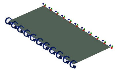
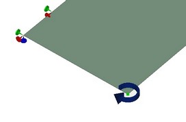
Torque, applied on edges (left) and at node (right)
A typical sequence of steps for specifying the load Torque at nodes:
1.Initialize the command "Torque at nodes" ![]() .
.
2.Select loaded edges or nodes of body.
3.Specify the units and magnitude of load.
4.Specify the axis of moment.
5.Complete the command.
See also: Mechanical Loads, Force, Pressure, Hydrostatic Pressure, Centrifugal Force, Gravity, Acceleration, Bearing Load, Torque, Torque at Nodes, Additional Mass, Remote Force, Remote Moment, Remote Mass