 |
AutoFEM Analysis Forced Oscillation of a Spring-Mass System | ||||||
Forced Oscillation of a Spring-Mass System
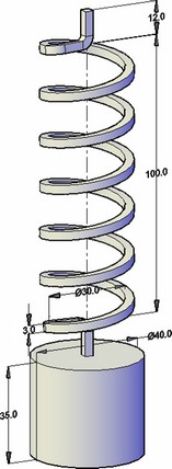
Let us consider a spring-mass system (see figure). This mechanical system is a classic example of an oscillation system with one degree of freedom. The behavior of this system is well studied and can be described by elementary trigonometric functions which are considered in classic physical and mechanic textbooks.

Let the vertical harmonic force is applied to the mass and the movement of the mass is allowed to be only along Z axis (vertical). The force varies with time by harmonic law:
F(t)=F0sin(ωft),
where F0 is equal to 10 N.
ωf= 2π ff ,
where the frequency ff ranges from 5Hz to 30Hz.
Our aim is to find oscillation amplitudes of the mass using the specified frequencies.
Let us use the following initial data: the mean diameter of the spring D is 30 mm, the length of the spring H is 100 mm, the cross section of the wire is a square with a side d=3 mm, the number of spring turns n is 6. Parameters of a weight are following: the diameter DW= 40 mm, height H=35 mm, mass mW= 0.34306 kg.
Parameters of the spring/weight material: modulus of elasticity E=2.1E+011Pa, Poisson's ratio ν=0.28, density ρ=7800kg/m3, shear modulus G=8.203E+010Pa, damping coefficient 2 % relatively the critical damping.
Classic analytical solving
Amplitude of forced harmonic oscillations for the system with one degree of freedom is described according next expression
 (1)
(1)
where ΔzF is a displacement under static force action, which is equal to amplitude of the harmonic driving force, ωf = 2*π*ff , ω0 = 2*π*f0- cyclic frequency of driving force and own frequency relatively; γ=c/ccr=0.02 - relative damping coefficient. Free oscillation frequency of the weight with the spring, which are considered as a system with one degree of freedom, is determined as next famous expression [1]:
![]() (2)
(2)
where g – free fall acceleration, m/s2; Δz – static displacement of the mass because of gravity action.
Static displacement is defined as [2]:
![]() (3)
(3)
where m – mass of the weight, kg; D – medium diameter of the spring, mm; n – the number of spring turns; d – cross section of the wire, mm; G – shear modulus, Pa.
The result of solving equation (3) gives static displacement of the weight because of gravity action
Δzg=0.451 mm.
Thus, the analytic solving of equation (2) gives next value of frequency for considered system with one degree of freedom: f0 = 23.457 Hz.
The displacement of the free end of the spring under static load can be calculated by the following formula:
![]()
where F is an axial force, N; D is the mean diameter of the spring, mm; n is the number of turns of the spring; d is the wire size, mm; G is the shear modulus, Pa.
Thus, static deformation under the static load ΔzF = 1.342 mm . If the resonance occurs (i.e. ff = f0), the vibrational amplitude is equal to Af=ΔzF/2γ = 33.55 mm.
Numerical solution
Let us solve this study by AutoFEM Analysis package. The top end of the spring is fully fixed. Displacements of the weight along X-axis and Y-axis are forbidden.
|
The finite element model with applied loads and restraints |
The static displacement of the system under the proper weight is Δz*g = 0.454 mm (the result "Displacement OZ" of the study "Static Analysis (gravity)").
First eigenfrequency is equal to f(1)c =23.594 Hz (the result "Mode 01 (23.637 Hz)" of the study "Frequency Analysis").
The displacement of the free end of the spring under static load is equal to Δz*F = 1.305 mm (the result "Displacement OZ" of the study "Static Analysis (force)").
Let the ratios of the Rayleigh damping have following values: α= 0.02, β= 2.6891E-004. These values correspond to 2% of the critical resistance.
The damping coefficient γ can be defined by following formula:
![]()
The vibrational resonance amplitude has the following value: A*f=32.36 mm .
Let us compare the results of calculation:
Table 1. Parameters of the finite element mesh
Finite element type |
Number of nodes |
Number of finite elements |
quadratic tetrahedron |
2675 |
6613 |
Table 2. The results
Type |
Numerical solution |
Analytical solution |
Error δ = 100* | R* - R | / | R |, % |
Δzg, mm |
0.454 |
0.451 |
0.67 |
f(1)c, Hz |
23.637 |
23.457 |
0.77 |
ΔzF, mm |
1.305 |
1.342 |
2.76 |
Table 3.The result “Amplitude”
Frequency, Hz |
Numerical solution |
Analytical solution |
Error |
5 |
1.358 |
1.4057 |
3.4 |
10 |
1.579 |
1.6396 |
3.7 |
15 |
2.169 |
2.2682 |
4.3 |
20 |
4.532 |
4.8773 |
7 |
f0=23.457 |
32.360 |
33.55 |
3.5 |
25 |
10.3 |
9.4208 |
9.3 |
30 |
2.115 |
2.1041 |
0.5 |
|
*The results of numerical tests depend on the finite element mesh and may differ slightly from those given in the table.
Read more about AutoFEM Oscillations Analysis