 |
AutoFEM Analysis Stresses of an Orthotropic Plate at Biaxial Tension | ||||||
Stresses and deformations of an orthotropic plate at biaxial tension

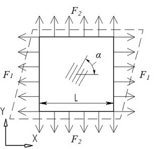
Let us consider a square plate made of the orthotropic material, with the length of the side L, which is loaded with forces F1 and F2, applied to edges of the plate. The width of the plate is h.
We need to define stresses and deformations of the plate. Assume F1=20,000 N, F2=10,000 N, L=0.1 m, and h=0.005 m.
The material’s parameters are as follows: Modules of elasticity are Е1=5.59·1010 Pa, Е2=1.373·1010 Pa, Е3=1.373·1010 Pa, modules of shearing are G12=5.59·109 Pa, G23=4.904·109 Pa, G31=5.59·109 Pa, and Poisson coefficients are ν12=0.277, ν23=0.4, ν31=0.068. The angle of elevation of the main axis of symmetry is α=45°.
At the center of the plate, let us create an user coordinate system (named "Ortho") using AutoCAD command "UCS" and then import it into AutoFEM Analysis.
This coordinate system will define the anisotropy axes of the material of our plate. To set them, we should use the context command "Anisotropy properties".
To stabilize the model, check the box "Stabilize the unfixed model" (page "Solve" of the study properties).
Apply normal load with magnitude F1 to one pair of parallel lateral facets, and normal load F2, to another pair.
|
The finite-element model of the orthotropic plate with loads and fastenings |
Let us carry out a static calculation for the plate with the use of the command “Calculation”.
We will obtain results in the form of deformations and stresses.
|
Principal stress 1 of the orthotropic plate |
|
Principal stress 2 of the orthotropic plate |
Average value of deformation ОХ εx*=3.177·10-4, of deformation ОY εy*=2.107·10-3,
Main stresses are: σ1*=4,000·107 Pa, σ2*=2,000·107 Pa.
The analytical solution for main stresses takes the following form:

where F1,2 means force N, L means length of the plate, and h means width of the plate, m.
σ1=20000/0.005/0.01=4·107 Pa, σ2=10000/0.005/0.01=2·107 Pa.
Deformations along the axes OX, OY are calculated using the following formulae:

ν21=0.277·1.373·1010/5.59·1010=0.06804
εx=3.0·107/5.59·1010 – 0.06804·3.0·107/1.373·1010=3.88·10-4;
εy=3.0·107/1.373·1010 – 0.277·3.0·107/5.59·1010=2.036·10-3;
After calculations conducted with the help of AutoFEM Analysis by the direct method, we have obtained the following results:
Table 1
Type of finite element |
Number of corner nodes |
Number of finite elements |
Quadratic tetrahedron |
1589 |
4632 |
Table 2
Principal Stress |
Numerical result, σ* |
Analytical result, σ |
Error, |
σ1 ,Pa |
4.0x10⁷ |
4.0x10⁷ |
0.00% |
σ2 ,Pa |
2.0x10⁷ |
2.0x10⁷ |
0.00% |
Table 3
Strains |
Numerical result, σ* |
Analytical result, σ |
Error, |
ε OX |
3.2396x10⁻⁴ |
3.88x10⁻⁴ |
16.51% |
ε OY |
2.1141x10⁻³ |
2.036x10⁻³ |
3.84% |
Conclusions:
The relative error of the numerical solution compared to the analytical solution is <1E-005% for stresses and 16.51% for strains when using quadratic finite elements.
*The results of numerical tests depend on the finite element mesh and may differ slightly from those given in the table.
Read more about AutoFEM Static Analysis