 |
AutoFEM Analysis Preparing Finite Element Model for Analysis | ||||||
The main purpose of the AutoFEM Preprocessor is preparing initial data on the physical problem to be analysed in the form of a finite element model, which would adequately reflect on the geometrical and physical properties of the part being modelled. This finite element model is then processed by the AutoFEM Processor, which results in a solution to the posed problem. Preparing a finite element model does not require specific knowledge on the finite element analysis from a user. It is conducted on the basis of a geometrical model interactively, using the Preprocessor commands, whose function is described in this chapter. Use of the Preprocessor results in a finite element model of the part, containing:
•a finite element mesh;
•materials data;
•boundary conditions, corresponding to the physical problem being modelled.
The order of building a finite element model in AutoFEM is arbitrary in most cases, meaning that the user can first build the finite element mesh, and then apply boundary conditions, or, on the contrary, first specify loads and restraints, and only afterwards generate a mesh of finite elements. Nevertheless, an unavoidable condition for a proper finite element model is the presence of all its required components – a mesh of finite elements (tetrahedra), material properties and external impacts on the system.
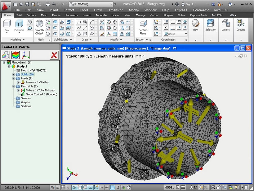
The mesh and boundary conditions are visually displayed in the Preprocessor window window directly (as the mesh) or by using special notations (boundary conditions). With this visual representation, the user can assess correctness of the data one specified.

Preprocessor window of AutoFEM Analysis: finite element mesh, loads, restraints,