| AutoFEM Analysis Remote Displacement | |||||||
| AutoFEM Analysis Remote Displacement | |||||||
Remote displacement permits one to transmit the effects of a known displacement of any remote structural member to the system, this member being connected to the structure by rigid connection. You can use this option when the replaced components are adequately rigid with respect to the modelled components and you know the remote translations and/or rotations that can replace its effect on the rest of the model.
It is assumed, that the point of application of the constraint is effectively connected to the selected faces by rigid bars.
The selected face(s), being rigidly connected to a common point, can only deform as a rigid body. The area and shape of each face remain unchanged. High stresses can emerge near faces with rigid connections.
To specify a remote displacement, use one of the following methods:
Command Line: |
_FEMAREMDISPL |
Main Menu: |
AutoFEM | Loads/Restraints | Remote Loads | Remote Shift |
Icon: |
|
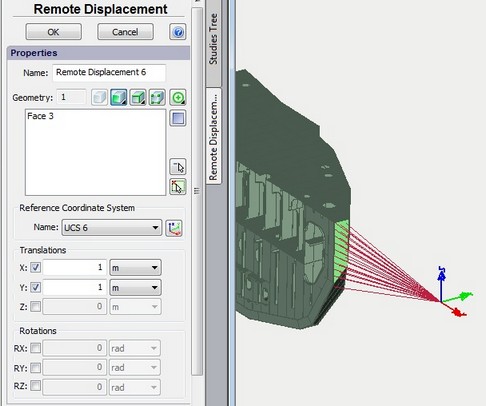
Defining Remote Displacement
A typical order of steps for defining remote displacement is as follows:
1.Create a reference coordinate system in the point of a remote shift application.
2.Initiate the command ![]() .
.
3.Choose the coordinate system to define the point of the restraint application.
4.Select entities of the model to be connected with the restraint.
5.Define the value of the remote displacement - translations and rotations.
6.Complete the command.
See also: User Coordinate System, Fixture