| AutoFEM Analysis Elastic Base | |||||||
| AutoFEM Analysis Elastic Base | |||||||
This type of restraint allows one to define the elastic interaction at the body’s boundary. The elastic base is used to model the touch of the body with the external elastic medium which is deformed together with the body. For instance, the building foundation and the building per se are deformed altogether with the earth on which it stands. Other examples of the body connected with the elastic medium are the dam, railway, etc.
From the mathematical viewpoint, the elastic base is considered to be a set of weightless springs of the predetermined stiffness, applied to the boundary of the body. The user must set forth the stiffness of the base using one of the two methods:
1.“Total” - the total value of stiffness in each direction shall be set. For the numerical work, this value is uniformly spread along the total area of facets/ total length of ribs/ total number of vertices.
2."Distributed" - it is used if the user knows the specific stiffness of the base per unit of area.
The direction of deformation of the elastic base can be set using the system of coordinates. For each axis of the selected coordinate system, the stiffness coefficient shall be set forth.
To set the elastic base, the following parameters are used:
Command Line: |
FEMASTIFFNESS |
Main Menu: |
AutoFEM | Loads/Restraints | Elastic Base |
Icon: |
|
In the dialogue of properties of this restraint, one must define facets, ribs or vertices of the body which contact with the elastic base.
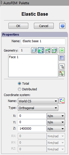
The typical procedure for setting the elastic base is as follows:
1.Initiate command ”Elastic Base” ![]() .
.
2.Select facets, ribs or vertices of the body.
3.Select the type of the stiffness coefficient: “Total” or “Distributed”.
4.Select the system of coordinates.
5.Set the value of the stiffness coefficient.
6.Complete the command.