| AutoFEM Analysis Step 1. Preparing Spatial Solid Model of a Part | |||||||
| AutoFEM Analysis Step 1. Preparing Spatial Solid Model of a Part | |||||||
Step 1. Preparing spatial solid model of a part
For analysis, you need to have a three-dimensional solid model of the part. The user can create the module in the AutoCAD three-dimensional modelling environment. This can be a "working" model, containing projections and complete working drawings, which could be part of an assembly. By using the AutoCAD command " File | Import ", one can load into the system a model for analysis, that was created in another spatial modelling system (*.sat ACIS format).
|
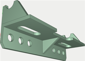
Original structure |
For calculation purposes, it is helpful to create in advance a special optimized version of the model (an optimized copy maintaining a parametric relationship with the original). For example, one can delete small features from the original model, which are not significant in the calculation (such as small unimportant holes). In this case, the calculations will run faster, and the finite element mesh can be created easier. To correctly apply loads, it is sometimes necessary to create special "spot" faces at some locations on large faces. |