| AutoFEM Analysis Thermal Contact | |||||||
| AutoFEM Analysis Thermal Contact | |||||||
No contact between material bodies can be considered ideal. Because of roughness of contact surfaces at the boundary between two bodies, microscopic gaps are formed, which are filled with air or another surrounding medium. This medium has heat conductivity coefficients which differ from the contacting solid bodies. As a result, a spasmodic change in the uninterrupted temperature field occurs at the border of the contacting bodies, which is typically caused by worse conditions of heat energy conductivity at this border. This physical phenomenon is called the thermal, or heat resistance. AutoFEM Analysis has a special command permitting to set a priori known values of thermal resistance and account for its influence on the transfer of thermal energy.
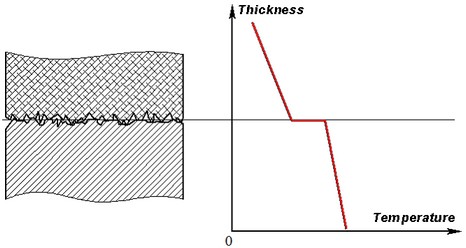
Change of temperature at the boundary surface of two bodies
The following command is predestined to set the value of thermal resistance:
Command Line: |
FEMATHERMALCONTACT |
Main Menu: |
AutoFEM | Loads/Restraints | Thermal Contact... |
Icon: |
|
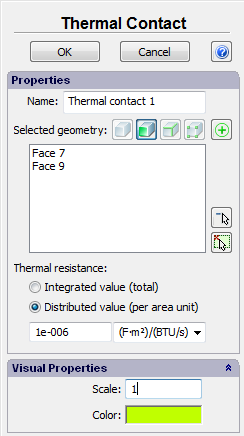
Click left mouse to specify facets of the bodies participating in the thermal contact. You may specify few sets of facets, for which thermal contact parameters are the same.
After that, you must choose the type of thermal resistance: integrated or distributed.
•Integrated resistance is measured with units deg/W. Its value characterizes total loss of thermal capacity through the entire boundary surface (the surface may be composite).
•Distributed resistance characterizes the loss of thermal flux, which falls upon the area unit of the boundary surface. Units of measurement are deg*m^2/W.
Certain reference values of thermal resistance coefficients are listed in the following table:
Materials of bordering facets |
Thermal resistance per area unit (m2 ·°K/ W) |
Iron/aluminum |
2.22·10-5 |
Copper/copper |
1·10-4 - 4·10-5 |
Aluminum/aluminum |
4.54·10-4 – 8.33·10-5 |
Stainless steel / stainless steel |
5·10-4 – 2.7·10-4 |
Stainless steel / stainless steel (sparse gaps) |
5·10-3 – 9.09·10-4 |
Ceramics/ceramics |
2·10-3 – 3.33·10-4 |
The typical sequence of actions required to set the thermal contact:
1.Initiate Command “Thermal contact” ![]() .
.
2.Select bordering facets of the bodies.
3.Define the type of thermal resistance (integrated or distributed) and its value.
4.Complete the command.