| AutoFEM Analysis Post-Processor Window Settings | |||||||
| AutoFEM Analysis Post-Processor Window Settings | |||||||
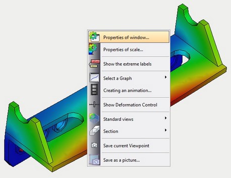
The viewer's settings are accessed by ![]() in the results viewer window from the context menu.
in the results viewer window from the context menu.
|
|
Dialog for customizing parameters of calculation results window |
|
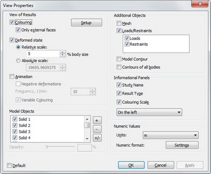
Parameters dialogue of the calculation results window has three groups of settings.
The «Viewing Results» group provides the following controls:
colouring. This flag toggles the mode of coloured rendering of the calculated model. colouring is done according to the properties of calculation results and settings of the colour scale. A colour filling some area in the model corresponds to a certain numerical value. colour scale setup is done in a separate dialogue (see below).
Only on Surface. Enables the mode of showing the mesh on the surface only. When the flag is off, the entire volume mesh is displayed.
Deformed State. This flag controls the way of rendering the resulting finite element model: it can be shown either in the deformed state, or as the original.
Scale. Sets the scale of deformations for the calculated model. It can be defined in terms of a relative or absolute value.
Initially, the scale is picked up by the system automatically, but the user can change it as desired. |
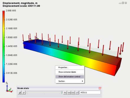
Animation. This flag turns on the animation mode of the postprocessor window, in which the deformation values smoothly vary from zero to the calculated value. To control animation and the deformed state rendering, one can also use a floating bar, that can be accessed from the context menu in the postprocessor window (the command «Strain state window» or «Time process window», depending on the type of the result).
Frequency. This parameter sets the rate, at which the full animation cycle completes. The number stands for the fraction of a minute, in which the full animation cycle completes.
Variable colouring. Controls colour variance during animation. Changes in colours can be synchronized with changes of the deformed state – from zero to final values. When showing negative deformations, the colours are not inverted.
Negative Values. This option enables the mode, in which the results displayed during animation first reach zero, and then go to the values equal to the calculated ones, but with the opposite sign. This creates the «vibration» effect of the calculated model, as if the load were periodically changing its sign to the opposite.
«Solids» lets you manage the bodies in the Postprocessor window, which are part of the assembly model, when evaluating assemblies. The user can tune of the flags corresponding to one or many parts of the assembly, after which those will no longer be displayed in the postprocessor window. By using the Opacity control, you can also manage transparency of the assembly parts displayed in the calculation results window. These tools help visualize the result fields inside the assembly model, by temporarily hiding obstructing objects.
«Display» group of parameters provides control elements, which define the visibility of auxiliary images around the calculated model for better results interpretation.
Mesh. Controls visibility of the mesh facets in the calculation results window.
Loads/Restraints. Controls visibility of all boundary conditions employed in the current study. The list of boundary condition types is displayed in a separate window. Visibility of each element in this list can be controlled individually. At the right of the window, there are buttons for managing the list elements. Using those buttons, you can enable (+), disable (-) or invert (+/-) visibility of all boundary conditions.
Model Contour. By enabling this flag, you make the contours of the original body subjected to the calculation appear as dotted lines in the calculation results window. This capability can be helpful for comparing the deformed state of the model with the original.
Contours of all Bodies. Upon enabling this flag, the rest of the bodies in the 3D scene, that were not subject to the calculations, are also displayed in dotted lines in the calculation results window.
«Information Bar» group of parameters contains controls for adjusting the amount of displayed textual and graphic information:
colouring Scale. This flag enables visibility of the colour scale for more intuitive interpretation of the calculation results. The scale range and colours can be customized (see «colour scale setup» below). The scale is displayed in the left of the calculation results window.
Study Name. This flag enables the display of the current study name in the calculation results window.
Result Type. This flag enables the display of calculation type name.
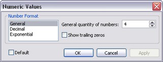
The "Number Format" group provides the following controls:
Units. Serves to define the measurement units (meter, inch, millimeter) to be used for displaying the result.
Format of Values parameter sets the format of the scale numbers for the viewing convenience - it can be decimal, exponential or general (mixed). The general format represents values up to the 1000 in the decimal format, those greater than 1000 - in the exponential format. The number of significant digits for the exponential format and the number of decimal digits for the decimal format are set in the provided field at the right. "Extra" zeros can be automatically discarded by disabling the flag "show trailing zeros".
See also: Processing Results