 |
AutoFEM Analysis Bending of a Simply-supported Beam Under Impact in the Middle | ||||||
Bending of a Simply-Supported Beam Under Impact in the Middle
Let us consider a simply-supported beam of L length on which the burden of M mass falls from the H height and impacts in the middle. Beam cross-section is a rectangle of b width and h height. We can neglect the beam mass.
|
It is necessary to define the beam maximum bending.
Let us consider L=1000 mm, b=50 mm, h=20 mm. The material properties are set by default. Modulus of elasticity E = 2E+011 Pa, Poisson ratio v = 0.29. The mass of burden is M = 79.42 kg. The height of burden fall is H = 4.0 mm.
Create Transitional processes study. The displacement of the lower edge of the left butt end is restricted by Z axis, the lower edge is fixed for the right butt. The load Acceleration of gravity is applied to the burden (as the beam mass can be neglected). The initial velocity of 280.1428 mm/s that corresponds to 4 mm of fall height is applied to the burden.
|
The finite element model with applied loads and restraints |
An analytical solution is the following:
![]() ,
, ![]()
where - ![]() a moment of inertia of the section.
a moment of inertia of the section.
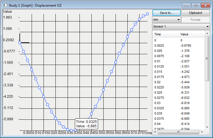
Let us find the step on which the maximum deviation by graph appears after calculation using AutoFEM Analysis:

After carrying out calculation with the help of AutoFEM, the following results are obtained:
Table 1.Parameters of the finite element mesh
Finite Element Type |
Number of Nodes |
Number of Finite Elements |
linear triangle |
1780 |
3186 |
Table 2.Parameters of temporal discretization
Total calculation time (s) |
Time step (s) |
Number of time layers |
0.08 |
0.0025 |
32 |
Table 3. Result "Displacement, OZ"*
Numerical Solution |
Analytical Solution |
Error δ =100%* |w* - w| / |w| |
6.885 |
7.2103 |
4.51 |
|
Conclusions:
The relative error of the numerical solution compared to the analytical solution is equal to 4.51% for quadratic finite elements.
*The results of numerical tests depend on the finite element mesh and may differ slightly from those given in the table.
Read more about AutoFEM Static Analysis