 |
AutoFEM Analysis Hollow Sphere Radiating Outwards | ||||||
Hollow Sphere Radiating Outwards
Let us consider a problem of determination of the steady-state temperature field of the hollow sphere, on the internal surface of which we maintain a constant temperature T1 =600 oK, and the external surface radiates to the ambient environment. The ambient environment has the temperature Tamb=290 oK. For this temperature the effect of radiation significantly changes the temperature inside the volume of the body. We can determine the temperature field at the control points with radii R123.
Characteristics of the sphere: external radius R=100 мм; internal radius R/2=50 mm; the thermal conductivity K=50 W/(m • oK); emissivity of the spherical surface is equal to α=1.
Let us consider a 1/8th part of the entire sphere. On the lateral surfaces of the sphere we prescribe the zero heat flux. (see figure).
|
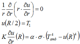
Since the material is isotropic, solution of the problem will depend only on the radius. If the origin of the spherical coordinate system is placed at the center of the sphere, we will obtain the equation with boundary conditions:

The solution of the equation has the form:
![]()
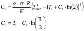
where the constants C1 and C2 are determined from the boundary conditions in the following way:

The first equation (for the given parameters) has two real roots . For the roots: C1 = -4483.400605 and C2 = -12831.06789 the solution on the boundary has the negative temperature on the boundary. For Kelvin scale it is impossible. Therefore, only the roots C1 = -13.02949201 and C2 = 560.9671302 satisfy this equation.
Let us compare the numerical solution with the obtained analytical solution at points with radii R123=0.0707106; 0.0848528; 0.0989949 m (coordinates of the sensors at these points: X123=50; 60; 70 mm and Y123=50; 60; 70 mm).
In the given points we will compare the numerical solution obtained using AutoFEM Analysis with the analytical solution.
|
|
The finite element model with applied boundary conditions |
After carrying out calculation the following results are obtained:
Table 1. Parameters of finite element mesh
Finite element type |
Number of nodes |
Number of finite elements |
linear tetrahedron |
1961 |
7187 |
Table 2. Result "Temperature"
Radius r, mm |
Numerical solution |
Analytical solution |
Error δ = 100%* |T* - T| / |T| |
0.0707106 |
585.6841 |
595.4843221 |
1.65 |
0.0848528 |
588.1666 |
593.1087648 |
0.83 |
0.0989949 |
591.5466 |
590.9686443 |
0.10 |
|
Conclusions:
The relative error of the calculations approaches 1.65%. Notice that when the mesh is refined, the numerical solution approaches the analytical solution slower because of the non linearity of the problem itself.
As we see, when computing the radiation, the relative error is practically the same for linear and quadratic elements. This can be explained by the error in the solution of the nonlinear equations. Thus, when computing radiation, it makes sense to use only linear elements because of smaller computational cost.
* The results of numerical tests depend on the finite element mesh and may differ slightly from those given in the table.
** Roots were found with the help of the Maple 9.5 system.
Read more about AutoFEM Thermal Analysis