 |
AutoFEM Analysis Specific Pre-Processor Settings | ||||||
Installation-specific settings of the preprocessor in Forced Oscillation Analysis
1.Limitation setting. The model may be restricted both by complete and partial limitations. When partial limitations are set, the setting of displacements other than zero is prohibited.
2.Force load setting. To set up the amplitude of force loads, the following types of loads can be applied to facets, edges or vertices of a model (acceleration can be applied to bodies):
•force;
•pressure;
•acceleration;
•cylindrical load
•torque.
A number of loads can action the system of bodies simultaneously, but all of them will have the same frequency. For each of permitted loads, its own initial phase of oscillations can be set.
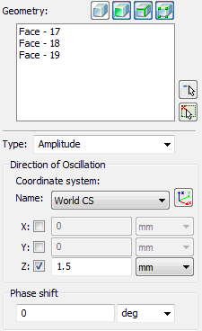
3.Kinematic load setting (oscillator). To set the oscillation amplitude of the support, one must apply the oscillator load to elements of the model, which can be used instead of full or partial fixing. The load is applied to facets, edges or vertices of the bodies, as well as to single bodies of the assemblage. In order to specify the direction of oscillations LCS is selected in the command, and the direction itself is stated by a check mark, corresponding to the relevant LCS axis. The type of kinematic load is selected from the drop-down list and might be as follows:
•amplitude of point displacements;
•velocity;
•acceleration;
•overload.

In the separate field, one can set the phase shift, measured either in degrees or radians.
At the combination of the oscillator load and partial fixings, directions of oscillations and limitations must be different for a single element of the model.
See also: Forced Oscillation Analysis, Theory Background, Steps of Oscillation Analysis, Settings of Oscillation Solver, Analysing Results