 |
AutoFEM Analysis Step 5. Defining Loads | ||||||
A set of special commands are provided in AutoFEM for defining loads, accessible from the menu " AutoFEM | Loads / Restraints ".
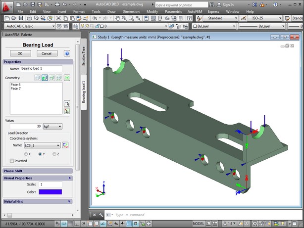
Using the "AutoFEM | Loads/Restraints | Bearing Load " command, select a face of the "Body", to which the load is applied. In the command's properties dialogue, specify the value of the load as 30 kgf. You need to define the load direction as well. Let's choose the y-Axis of the pre-created user coordinate system.

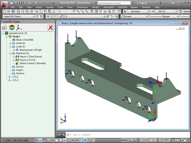
Upon completion of the loads creation command, the introduced loads are shown by special marks on the three-dimensional model of the part, applied to the appropriate model elements.

Upon a successful completion of the loads creation command, there are all four elements in the studies tree, required for running the calculations: mesh; material; restraints; loads.