 |
AutoFEM Analysis Step 4. Defining Restraints | ||||||
Step 4. Applying boundary conditions. Defining restraints
In order to successfully solve a physical problem in a finite element formulation, in addition to creating a finite element mesh it is also necessary to correctly define the so-called "boundary conditions". In statics, their role is played by restraints and external loads applied to the system.
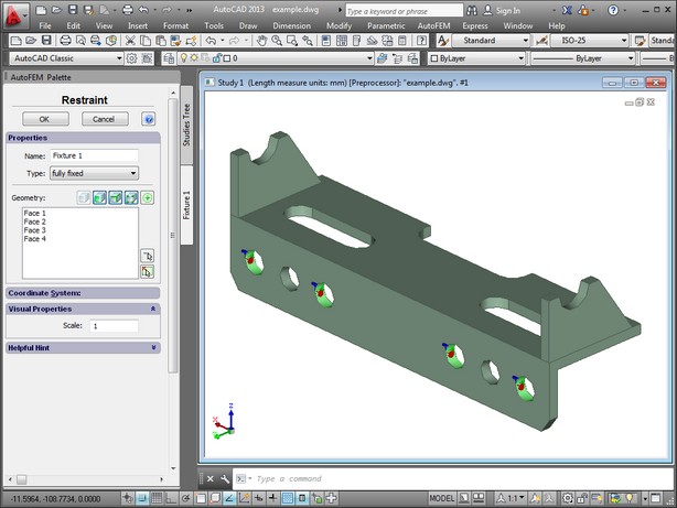
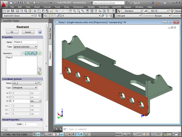
Two commands are provided in AutoFEM for defining restraints: "Fixture" and "Contact". The "AutoFEM | Loads/Restraints | Fixture"command is used with the model's vertices, faces and edges. It asserts that a given element of the three-dimensional body is fully or partially fixed. The fully fixed restraint does not let the element change its location under the impact of loads applied to the system. The partially fixed restraint does not let the element change its location along axes X, Y or Z (it depends on a selected axis).


When defining boundary conditions, the finite element mesh gets automatically hidden in order to let you apply boundary conditions to elements of the three-dimensional solid model (faces, edges, vertices).
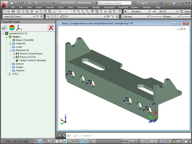
Upon successful completion of the restraints creation command, the corresponding elements are displayed in the studies tree of the studies window, signifying presence of the respective boundary conditions. Restraints on the face are also displayed by special three-dimensional elements (decorations) in the model window of AutoCAD.
