| AutoFEM Analysis Creating shell study based on 3D solids | |||||||
| AutoFEM Analysis Creating shell study based on 3D solids | |||||||
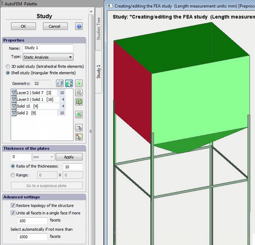
To create the study, based on triangular finite elements using solid facets, perform the following sequence of steps:
1)Initiate the command of creating Study
2) Create the set of objects from solids (if the set of objects for FEA already exists, this step will be automatically excluded).
3)Then, in the dialogue of study creation, turn on the filter ![]() and choose the mode of faces selection - single face selection or multiple selection,
and choose the mode of faces selection - single face selection or multiple selection,
4)In the Preprocessor window, click on those facets which are to be covered by the study. You should take into consideration that the study will be created precisely on the basis of spatial coordinates of the selected facets (and not of the medial plane of thin-walled objects). This affects the result. However, in real thin-walled structures, dimensions of a product significantly (e.g., by hundreds of times) exceed the thickness of such a structure. In this case, the change of dimensions by half sheet thickness can be often ignored.
Note! Check the integrity of the calculated model. All the selected facets must be tied with one another.
Creation of the study using facets of solid-object models
5)Use the mode of the filter “Choose only adjacent facets” ![]() for inclusion adjacent facets between the solids into the study.
for inclusion adjacent facets between the solids into the study.
Selecting adjacent facets.
6)Use the button “Add all non-selected adjacent facets in the contact area of 3D solids” ![]() to ensure integrity of the shell model.
to ensure integrity of the shell model.
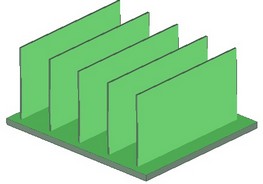
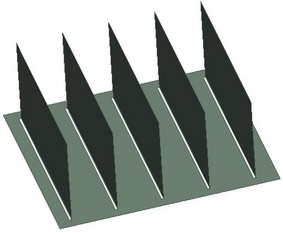
The use of this option can be shown using the following example. Consider the thin-walled 3D model, which we can model (with acceptable accuracy0 using lamellar elements (a heat-removing radiator). If we create a study selecting the bottom facet of the base and facets of heat-removing ribs, then “holes” will appear where ribs contact. Pressing ![]() launches the process of automatic search and addition of facets, covering these holes, to the study. This significantly simplifies preparation of the lamellar calculated model using solid-body models for real practical structures.
launches the process of automatic search and addition of facets, covering these holes, to the study. This significantly simplifies preparation of the lamellar calculated model using solid-body models for real practical structures.
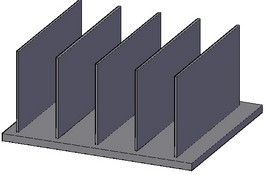
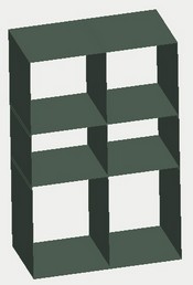
Initial 3D model
Selection of main facets for the calculated model
Shell calculated model before the option
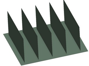
Calculated model after the option
6) Set up the thickness of plates and shells of the structure (see also). The system will not allow you to drop the command if there are objects with the undefined thickness. The thickness of the plate can be changed after the study was created.
7) Let us consider the destination of fields in the group Advanced settings.
Option Unite all facets in a single face is designed to optimize the work with hull parts of the ShipConstructor, which often contain several thousand facets, and each facet is seen by AutoCAD as a separate object. With this option selected, all of the numerous subfacets of one solid are integrated in a single face. It provides the opportunity to apply a load to the solid’s face on the whole, regardless of the number of facets properly approximating its geometry. The default threshold value equals 100.
Option Restore topology of the structure switches on the mode of restoring points of contact between parts when transforming the solid-body model of the structure into its shell equivalent. Let us consider illustration below.
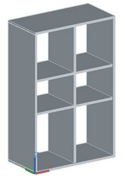
Original structure
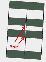
"Restore topology" is switched off.
There are gaps in the estimated shell model
"Restore topology" is switched on.
The topology corresponds to the original 3D model
There are some limitations of the restore topology option:
•at the moment it works with the flat sheet parts;
8) Press OK to complete the command and create the study.
See also: Set of objects for FEA, Creating Study, Creating study based on 3D solids (tetrahedral elements), Creating study based on surface 3D models, Assigning Thicknesses