| AutoFEM Analysis Sections | |||||||
| AutoFEM Analysis Sections | |||||||
AutoFEM Analysis offers the possibility of constructing sections of the finite-element mesh by the user-set plane. In the Preprocessor, a section can be used to obtain access to internal cavities of the model, to which boundary conditions are to be applied. In the Postprocessor, using the section, one can analyse a result obtained inside the finite-element model. Thereat, the numerical value of the result in the section place is reflected with the help of a tool tip. To analyse the result in the section plane one may also use the sensors by preliminary defining their location inside the model.
To construct the section, it is necessary to select the command “Section | Show / Hide section” in the context menu retrieved by pressing the right button of the mouse in the window of preprocessor / postprocessor.
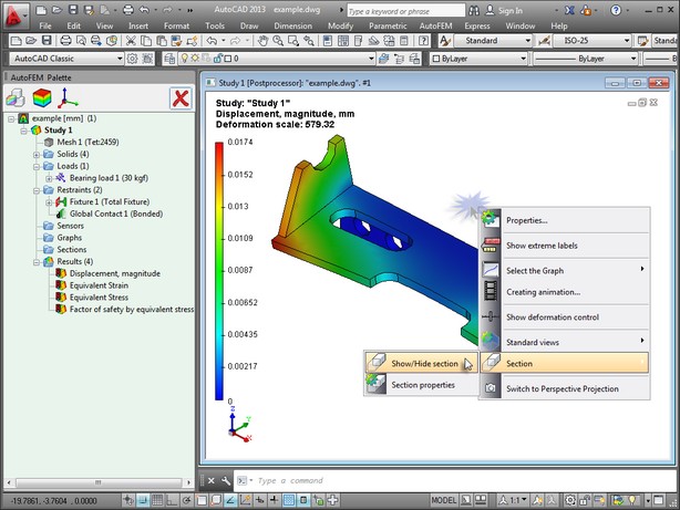
Activation of the command to construct the sections in the Postprocessor window.
Then, after activating the required control element, by moving the mouse cursor in the vertical direction, you should set the section plane in the required position. To rotate the plane relative to the set system axes, there are control objects: ![]() ,
, ![]() ,
, ![]() . To move the plane along the axes of the system of coordinates, the control objects are provided:
. To move the plane along the axes of the system of coordinates, the control objects are provided: ![]() ,
, ![]() ,
, ![]() . The colour of each object corresponds to the colour of the axis (OX,OY,OZ) of the system of coordinates. The active element of control is marked against the background of inactive elements with the bold script.
. The colour of each object corresponds to the colour of the axis (OX,OY,OZ) of the system of coordinates. The active element of control is marked against the background of inactive elements with the bold script.
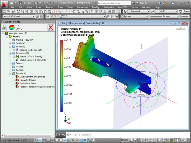
Control elements for the orientation of the section plane.
In order to hide the control objects, the command “Section | Show / Hide section controls” is used. The controls will be hidden, and the section plane will be constructed.
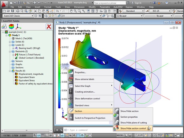
Governance of visibility of section controls.
There is also the possibility to construct the section plane relative to a certain system of coordinates. To do this, while being located in the command of section construction, you must select the command “Section | Section properties” in the context menu in the preprocessor / postprocessor window.
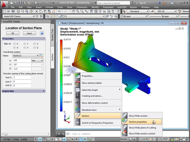
Access to section properties from the context menu.
Then, in the group ”Coordinate system”, you need to state the system of coordinates, relative to which the section will be constructed, and set the position of the section centre in this coordinate system. Additionally, you may select the axis of the coordinate system which will be normal to the cutoff plane (the ”Align to” parameter)or set the orientation of the normal against the slice plane via the ratio of the normal’s projections on the axis of the coordinate system. So constructed section is saved in the task tree in the grouping folder ”Sections” when you press ![]() .
.
Using the command “Move to”, retrieved from the context menu at the required section in the task palette, the User may at any time open the section with the earlier saved orientation.
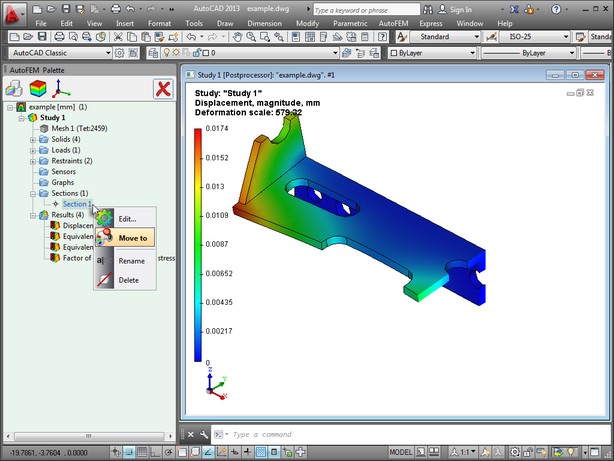
Moving the section to get the saved orientation.
Using the command ”Edit...”, you can change the orientation of the earlier created section. Editing the orientation of the section is performed in the Preprocessor window. Because there is no result shown in the Preprocessor window, parts of the model, falling in the section plane, are not shown.
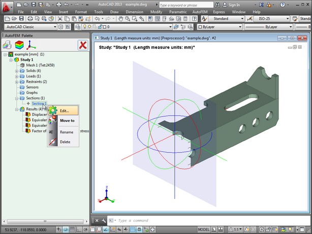
Retrieving the command to edit the section orientation.
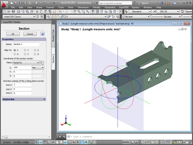
Editing parameters of the section saved in the Preprocessor window
See also: Processing Results