 |
AutoFEM Analysis Bar Subjected to Self-Weight | ||||||
Bar Subjected to Self-Weight
Let us consider a bar of radius R and length L, suspended at the upper edge and stretched under the action of self-weight (see figure).
|
||
The finite element model with applied loads and restraints |
Let us use the following data: length of bar L is equal to 1 m, radius of cross-section of the bar R is equal to 0.02 m.
Material characteristics: E = 2.1E+011 Pa, ν = 0.28, ρ = 7800 kg/m3 .
Total elongation of the bar under the action of the self-weight can be determined from the formula:
ΔL = γL2/2E,
where γ – specific weight of the bar's material, that is γ = ρg, g ~ 9.80665 m/s2.
The stress in the cross-section of the bar located at a distance x from lower (unconstrained) edge can be evaluated from formula:
σ = γx
Thus, ΔL = 1.8212E-007 m; σ = 3.8246E+004 Pa at x = 0.5L.
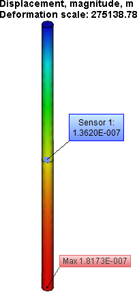
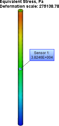
After carrying out calculation with the help of AutoFEM, the following results are obtained:
Table 1.Parameters of finite element mesh
Finite Element Type |
Number of nodes |
Number of finite elements |
quadratic tetrahedron |
440 |
972 |
Table 2.Result "Displacement, magnitude"*
Numerical Solution |
Analytical Solution |
Error δ = 100%* |w* - w| / |w| |
1.8173E-007 |
1.8212E-007 |
0.21 |
Table 3. Result "Equivalent Stress"*
Numerical Solution |
Analytical Solution |
Error δ = 100%* |σ* - σ| / |σ| |
3.8246E+004 |
3.8246E+004 |
0.001 |


Conclusions:
The relative error of the numerical solution compared to the analytical solution is 0.21% for displacements and 0,001% for stresses when using quadratic finite elements.
*The results of numerical tests depend on the finite element mesh and may differ slightly from those given in the tables.
Read more about AutoFEM Static Analysis