 |
AutoFEM Analysis Anisotropic Materials | ||||||
Anisotropic materials differ from isotropic ones in that their physical properties (elasticity moduli, Poisson coefficients, heat conductivity, etc.) have different values depending on spatial orientation of the physical body. Among the variety of anisotropic construction materials, of the greatest practical value are the so-called orthotropic and transversally isotropic materials. AutoFEM Analysis provides for the involvement of both types of these anisotropic materials in the study.
Orthotropic materials
The orthotropic material is a type of the anisotropic material, which has three mutually orthogonal planes of elastic symmetry, along which its characteristics remain unchanged. Such materials include various crystals and composite materials with a regular structure (e.g., layered glass-reinforced plastic or tissue glass-reinforced plastic).
For the orthotropic materials, the generalized form of the Hooke law can be put down as follows:
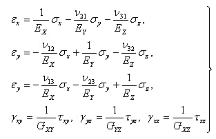
Out of 12 coefficients of this equation (elastic constants), only nine are independent, since for the symmetry of the right term of the equations of generalized Hooke’s law, the following ratios take place:
![]()
Shear moduluses Gij are independent of other elastic constants.
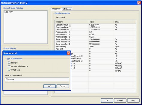
To set up the orthotropic material, when creating it, one should define its type as “Orthotropic”. Then, one should set up the physical properties of the material along each axis.
Transversally isotropic materials
The transversally isotropic material is a variety of the anisotropic material, for each point of which there is a plane of elastic symmetry, at which, along all directions, characteristics of the material do not change. In other words, two out of three coefficients of elasticity of such material are equal E=Ex=Ey, while the third is not: E'=Ez -. Such materials include, for example, wood made of logs (Ez is directed along the radius), paper, and plywood (E'=Ex=Ey in the plane of the plywood, and E=Ez in the direction perpendicular to the plane of the plywood sheet).
For the transversally isotropic materials, the generalized Hooke law looks like:
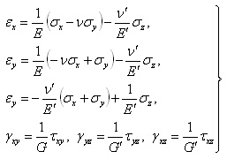
The transversally isotropic material is characterized with the following elastic constants: modulus of elasticity E, Poisson coefficient ν, and rigidity modulus G, active in the planes of symmetry; thereat,
![]()
 .
.
In all planes, which are orthogonal to the symmetry ones, functioning are elasticity modulus E’, Poisson coefficient ν’, and rigidity modulus G’, and for certain materials, the equation may be satisfied:
![]()
 .
.
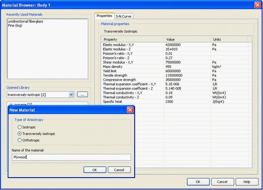
In order to set up the transversally isotropic material, when creating one, one should select the type «Transversally isotropic”, after which the dialogue for setting up the material’s properties will appear.
Setting up axes of elasticity (anisotropy)
At solving problems which include bodies made of anisotropic materials, it is crucial prior to calculation to correctly determine the major directions of elasticity for each body.
For this purpose, the user need to select the “Anisotropy properties” item in the context menu located on the body (or a group of bodies) with the assigned anisotropic material. Concerning the properties of the material, the type of the latter should be selected: “Orthotropic” or “Transversally isotropic”.
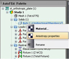
In the opened dialogue, the user must select the local system of coordinates, whose axes coincide with the orientation of main axes of elasticity of the orthotropic material.
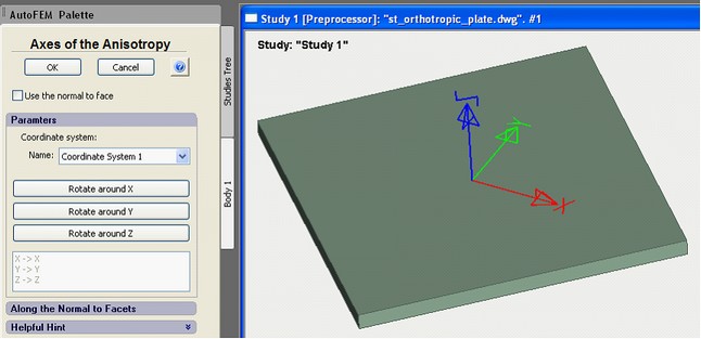
Directions of elasticity axes are determined by the coordinate system, preset for each body. The same orthotropic material can be preset for few bodies, and for each body, the directions of symmetry axes can be set by the separate coordinate system. The main directions of elasticity (normal to the symmetry planes) will be oriented along the axes of the coordinate system, listed for the body. The default elasticity axes coincide with the axes of the Global system of coordinates.
Buttons “Rotate around X, Y, Z...” set up the turn of the material’s elasticity axes relative to the axes of the selected coordinate system.
To view what system of coordinates is related to a given orthotropic body, one should anew invoke the Anisotropy properties command for the body in the tree of studies.
For the transversally isotropic bodies, there is an option to set up the anisotropy parameters based on the body’s geometry. To do this, in the command for setting the axes of anisotropy, the user must choose regime "Use the normal to face" and select facets, the normal to which will set the direction E'=Ez.
This method permits to define the parameters of the transversally isotropic material for bodies of the complex spatial configuration, including curved forms.
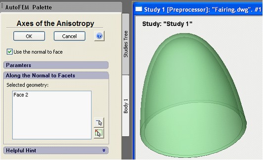
A fairing made of the transversally isotropic material.
The anisotropy axis coincides with the normal to the surface
See also: Assigning Material, Creating New Material, Creating New Material from Template, Temperature Curves, S-N Curve, Assigning Thicknesses, Export / Import of Materials, Getting Materials from ShipConstructor, Physical Properties