 |
AutoFEM Analysis Dialogue and Selection Tools | ||||||
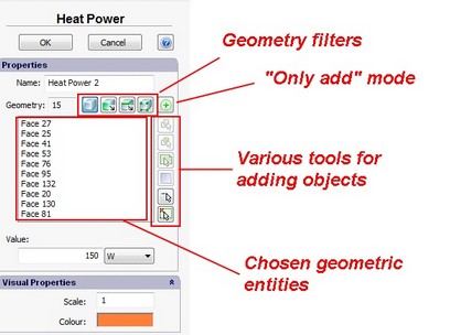
Consider this typical dialogue for setting the boundary condition, using an example of the dialogue called “Heat Power”.

Dialogue for setting the boundary condition “Heat Power”
The main parameters determining the boundary condition lie in the group named "Properties".
The field “Name” contains the name of the boundary condition in the form which it will take in the tree of studies. The user may edit that name at their own discretion.
The number near the field “Geometry” shows the number of selected objects.
The list reflects elements of the model, which have been selected by the user.
Above the list corresponding to the selected geometry, there are buttons![]() , switching on the mode for filtering geometric entities in the 3D model by the type of geometry (body, facet, edge, or vertex), together with the button
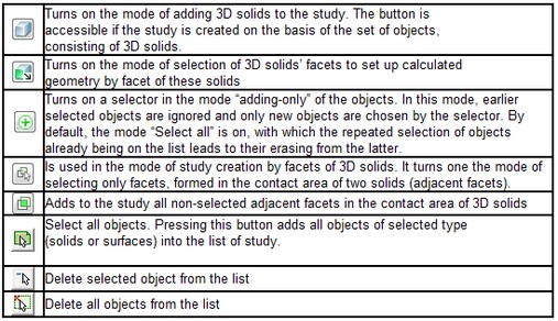
, switching on the mode for filtering geometric entities in the 3D model by the type of geometry (body, facet, edge, or vertex), together with the button ![]() , intended for switching on the mode “Only add objects " (see the Table).
, intended for switching on the mode “Only add objects " (see the Table).
On the right of the selected geometry list, there are buttons for the automatic selection of geometric entities ![]() by various criteria, and buttons
by various criteria, and buttons ![]() and
and ![]() for eliminating the entities from the list.
for eliminating the entities from the list.
In general, the boundary conditions can be applied to the bodies, facets, edges or vertices of the 3D model. Pressing the button with the relevant pictogram (see the Table) turns on the mode for selecting the relevant geometry. For each boundary condition, there are only those selectors which are applicable to the given boundary conditions. For instance, in the Force and Pressure load, one cannot select the mode of bodies’ selection and, vice versa Acceleration (force of gravitation) cannot be applied to the facet or edge of the model.
The choice of objects to which the boundary condition is to be applied is made in the “Preprocessor” window. The system will automatically highlight the object under the cursor of the mouse, after which a left click adds the object to the list. The click repetition? on the earlier selected object leads to the latter’s exclusion from the list of the chosen geometry.

![]()
There are additional options for the modes of selecting facets and edges of the model:
The additional options for automatic selection of elements include the ability to choose elements of a 3D model, lying on one plane, as well as to make multiple choices of facets (for thermal studies).
Also see: Means of geometry selection, Dialogue and Selection Tools, Frame Selection Tool, Selection of facets, Selection of edges, Selection in plane, Multiple choice of faces,