About us
Who are we?
Where are we located?
Is it possible to become your dealer?
What are advantages of cooperation with us?
How to buy AutoFEM Analysis?
General Questions
Where can I get the support concerning AutoFEM?
What versions of AutoCAD does AutoFEM Analysis work?
I'm working with another CAD system (Inventor,Mechanical Desktop, Solidworks). Can I use AutoFEM?
I have installed AutoFEM, but it seems, that Fema Tool does not work. What may be wrong?
I have installed AutoFEM to try it in a trial mode and during a start of AutoFEM I see the message box about license server. What should I do?
I have started the AutoCAD after AutoFEM Analysis installation but I don’t see menu or ribbon of the AutoFEM Analysis, what is wrong?
I have typed FEMAABOUT but I don't see the dialogue "About AutoFEM". What can I do now?
To restore the original AutoCAD menu after removing AutoFEM Analysis...
Could AutoFEM Lite version be installed simultaneously with AutoFEM Commercial (Trial) on one computer?
What are the recommended system requirements for work with AutoFEM Analysis?
Does AutoFEM work with AutoCAD 2011?
Does AutoFEM Analysis work with AutoCAD Lite?
Is the AutoFEM license perpetual?
Around FEA modeling
Requirements for the three-dimensional model for finite element analysis
I have a study but I couldn't create FE mesh. What can I do?
Should direct or iterative method be used for solving?
How can I apply a force (or pressure) to a certain area of the part?
About us
Who are we?
AutoFEM Software is a team of mathematicians and gifted programmers who have engaged in the development of applied software complexes for finite-element modelling for a long time. Until recently, our developments in the field of computations were sealed and occurred within the framework of development of private corporate design systems. AutoFEM Analysis is developed specifically for a broad audience and is oriented towards experts living and working in different countries throughout the world.
Where are we located?
The company is legally incorporated and located in London (UK), and we work in compliance with the law of the United Kingdom and EC. However, on the whole, our company is international and some of the Technical Support Service staff may reside in different countries and time zones. Therefore, e-mailing is the preferable type of communicating us. Generally, we answer the request within several minutes or hours, especially fast if this request comes from the Eastern hemisphere.
Is it possible to become your dealer?
Yes, it is. We offer up to 50% discount on software to our partners-resellers. If you wish to become our dealer, contact us in any way available to you: via the “Contact” form on our website or by e-mail to the Technical Support Service. We will discuss all necessary formalities.
What are advantages of cooperation with us?
We are the harmonious company consisting of developers and programmers. This means that we can dynamically react to your questions and wishes how to improve our products. We can develop an additional specialised functionality, if our users need it. We can do it as fast as you want and make it relatively cheap (surely, if we agree with the feasibility of the study). This is our fundamental advantage before any other CAE company.
How to buy AutoFEM Analysis?
There are two main ways to pay for the commercial version and get the licence key.
Way One. You can use services of registration company ShareIt!. The major advantages of buying the licence via ShareIt! :
- Variety of payment options. These companies accept different kinds of electronic payments, bank cards as well as non-cash bank transfers. They also offer the buyer all necessary accounting documents (invoices, etc.), if you need them.
- Fixed value. RegNow and ShareIt! provide licences for AutoFEM Analysis at the same cost which is stated on our website. If you need a non-standard set of modules which is not available on the registrar’s website, please write Questo indirizzo email è protetto dagli spambots. È necessario abilitare JavaScript per vederlo., and we will accept it as individual order.
- Rate of purchase. If you pay via electronic transfer (e.g., PayPal) or from the credit card, then, as a rule, the license key will be given to you by an email as soon as in few minutes after the payment is made.
- Security. The purchase via RegNow or ShareIt! is the safest way of obtaining the licence for AutoFEM Analysis, as you pay money to the mediator, who can be an independent arbitrator and, thus, guarantee that you necessarily get the licence key with the configuration you have ordered.
Way Two. You can pay the value of the licence directly to the account of our company (AutoFEM Software LLP). You only need to request it via email Questo indirizzo email è protetto dagli spambots. È necessario abilitare JavaScript per vederlo., and we will post you the bill. The order must state:
- Name and registered address of your company;
- Name of the company leader;
- Name and contacts of a person who will solve technical problems;
- Strict configuration (set) of modules which you wish to buy and their number; and
- What additional accounting documentation you need.
After you pay our bill, we will send you the electronic key and necessary documents.
General Questions
Where can I get the support concerning AutoFEM?
If you encounter difficulties installing or using AutoFEM, the best way to try to resolve them is to go directly to our technical support email: Questo indirizzo email è protetto dagli spambots. È necessario abilitare JavaScript per vederlo.. Please, be clear in describing your problem and tell us the version of Windows, AutoCAD and AutoFEM, that you are using. We strongly recommend you to immediately contact with us instead of searching with Google all questions, concerning AutoFEM installation and etc. It is more effective and gives the results.
What versions of AutoCAD does AutoFEM Analysis work?
The system of finite element analysis AutoFEM Analysis 3.x works with AutoCAD x64 2010, 2012, 2013, 2014, 2015, 2016, 2017, 2018, 2019, 2020 for Windows based operational systems on 64-bit platform.
I'm working with another CAD system (Inventor,Mechanical Desktop, Solidworks). Can I use AutoFEM?
AutoFEM Analysis works only in AutoCAD's 3D environment, it does not work directly with Inventor, Mechanical Desktop, SolidWorks etc. However, if you have the possibility to use AutoCAD, you can export your 3D model from CAD system into AutoCAD via SAT file format (ACIS exchange file format) and then you can try to carry out finite-element analysis of your model using AutoFEM.
I have installed AutoFEM, but it seems, that Fema Tool does not work. What may be wrong?
Sometimes, you should install the Microsoft Visual C++ 2008 SP1 Redistributable Package x86 or the Microsoft Visual C++ 2008 SP1 Redistributable Package (x64) before AutoFEM installation. Also you can find these packages in the AutoFEM distribution package or you can download them from our site: vcredistx86_2008 or vcredistx64_2008.
I have installed AutoFEM to try it in a trial mode and during a start of AutoFEM I see the message box about license server. What should I do?
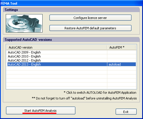
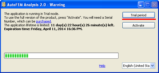
If you see the following message while AutoFEM is starting, it means that the software is trying to use license server to get the license.
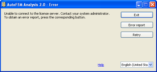
To run the software in trial mode, use the following steps.
1. Open the window of AutoCAD / AutoFEM registration settings and press the button "Configure licence server"

2.Tick the flag "Server-side activation" and then uncheck it to confirm that we don't use the license server.
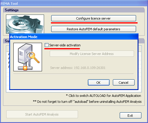
3. Now you can try to run AutoFEM Analysis in the trial mode.
I have started the AutoCAD after AutoFEM Analysis installation but I don’t see menu or ribbon of the AutoFEM Analysis, what is wrong?
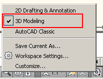
Firstly, it is necessary to check, has been AutoFEM loaded into AutoCAD or it has not. Type the command FEMAABOUT in the AutoCAD command line. If you see the dialogue as it is shown below it means that AutoFEM has being loaded and you don't see the Ribbon. In such case, normally, it is sufficient to reload 3D Environment of AutoCAD and the AutoFEM Ribbon and menu will appear.
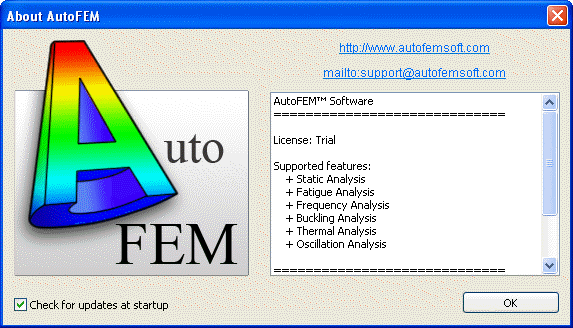
If the dialogue "About AutoFEM" appears this means that AutoFEM is loaded successfully
Reloading the 3D Environment of AutoCAD to activate AutoFEM Ribbon and menu
I have typed FEMAABOUT but I don't see the dialogue "About AutoFEM". What can I do now?If AutoCAD says "Unknown command" after the typing FEMAABOUT, this means that AutoFEM has not been loaded for any reasons. However, you can try to load AutoFEM manually using the AutoCAD command APPLOAD and choosing the file:
... Program Files\AutoFEM Software\AutoFEM17.arx - for AutoCAD 2007, 2008, 2009or
... Program Files\AutoFEM Software\AutoFEM18.arx - for AutoCAD 2010, 2012.
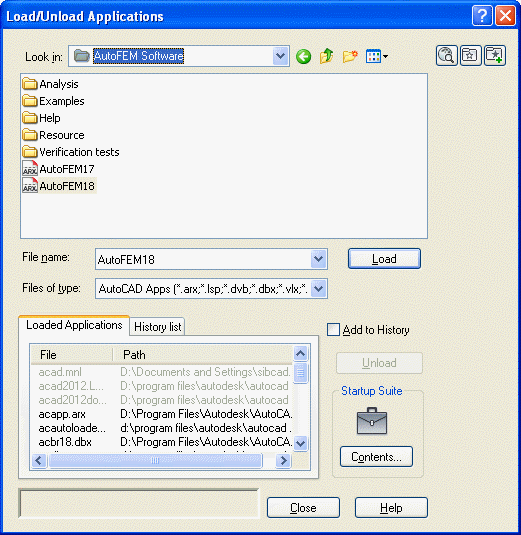 Using the command APPLOAD of AutoCAD
Also, you can try to add AutoFEM17.arx or AutoFEM18.arx file into the "Startup Suite" as it is shown below.
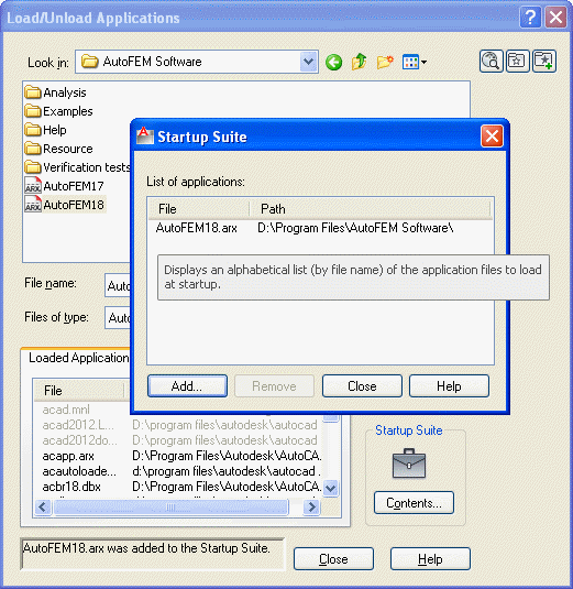
Adding AutoFEM ARX file in startup list
If this does not work, please, contact with our Support Service via the contact form on the site or E-mail: support@ autofem.com.
Please, provide us the next information:
- Windows version;
- Specify Windows bit capacity (x32 or 64-bit);
- Language pack of Windows;
- AutoCAD version;
- AutoCAD bit capacity (x32 or 64-bit);
- Language pack of AutoCAD.
We will help you to check installation and start up AutoFEM.
To restore the original AutoCAD menu after removing AutoFEM Analysis...
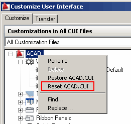
To restore the original AutoCAD menu after removing AutoFEM Analysis one must call the commands AutoCAD "cui" and "reset" as shown in the figure.
Could AutoFEM Lite version be installed simultaneously with AutoFEM Commercial (Trial) on one computer?
It is possible only if you will install different versions of AutoFEM in terms of bits - x86 or x64, for AutoCAD x86 and AutoCAD x64, respectively. It is impossible to use AutoFEM Lite and AutoFEM Commercial (Trial) for the same version of AutoCAD simultaneously.
What are the recommended system requirements for work with AutoFEM Analysis?
Mathematical modelling of physical phenomena belongs to the class of the resource-intensive problems that require serious computational resources. That is why, for efficient use of the finite element modelling system it is recommended to use the most powerful computers accessible to the user. Moreover, increase in the dimensionality of the solved problem can be achieved by using 64-bit operating systems.
AutoFEM Analysis is available in two versions depending on the edition of the Windows operating system:
| 1. |
AutoFEM for Windows 32-bit («standard» Windows, for example, for computers Pentium III or IV). The distinctive feature of the 32-bit operating systems is the existence of «physical» bound on the maximum volume of addressed information (about 2 GB), which limits capabilities needed for analysis of systems with large number of finite elements.
|
| 2. |
AutoFEM for Windows 64-bit (Windows XP 64-bit, Windows Vista 64-bit and etc.). This system works on the processors that support 64-bit instructions (for example, Intel Pentium D, Intel Core2Duo, AMD 64 and others). Operating systems with digit capacity 64-bit allow the user to address significantly larger volumes of information and solve the problems of higher dimensionality. |
Recommended computer parameters for efficient (professional) work with AutoFEM Analysis
|
Processor
|
with support of 64-bit instructions (Intel Core2Duo, AMD 64 and others)
|
|
Hard drive space (for storing calculation results)
|
500 GB and higher
|
|
RAM
|
32 GB (and larger)
|
|
Operating system
|
Windows 64-bit (Windows XP, Windows Vista, Windows 7)
|
|
Software
|
AutoCAD x64, AutoFEM x64
|
Does AutoFEM work with AutoCAD 2011?
No, it doesn't at this moment.
We were forced turn off AutoFEM loading in AutoCAD 2011 x86 because there are some problems of compatibility.
Therefore, AutoFEM Analysis does not work with AutoCAD 2011 x86/x64. Only AutoCAD 2007-2010, 2012,2013 are fully supported.
Does AutoFEM Analysis work with AutoCAD Lite?
No, it doesn't. AutoFEM Analysis and AutoFEM Analysis Lite can be used only with full version of AutoCAD because the 3D modelling workspace is necessary for finite-element analysis.
Is the AutoFEM license perpetual?
Yes, it is.
Each customer gets perpetual license. All updates within the main version number (1.1, 1.2, 1.3...) are absolutely free of charge.
Licensing is provided by the serial number which customer obtains upon confirmation of his/her payment.
The license can be moved to the other computer system through deactivation process (10 deactivations are provided).
If you have any difficulties with managing your license, please contact our support team.
Around FEA modeling
Requirements for the three-dimensional model for finite element analysis
The quality and possibility of constructing a finite element mesh is strongly dependent on the quality of volume models, so when building 3D models imposed more stringent requirements than conventional modeling in AutoCAD. You should consider the following requirements to create three-dimensional models of your products in terms of finite-element analysis.
- Mutual or self-intersection bodies are not allowed. It is impossible to construct a finite element mesh for intersecting bodies. Before you create a study, you always should test your model on the intersections by special AutoCAD command INTERFERE. This command shows intersections between bodies if they are. One advice is how intersections may be removed from the assembly if intersecting bodies consist of the same material. You can use the command of AutoCAD: UNION and unite intersecting bodies in a whole body.
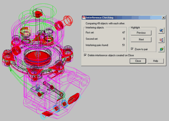
There are lots of intersections. Creating a finite element study impossible.
- Between the bodies must be no gap, except when there are no actual gaps between the bodies. All bodies, which are included in a study, must have a contact by a face, or edge, or vertex, with any other body of the study. So in the study, a totally unengaged body should not exist as it is like freely “hovering” in space.
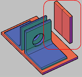
The models with gaps are not allowed.
- 3D body should be singly closed volume. Volume finite element mesh can be built only for a limited volume.
- In AutoCAD one can create a solid 3D model which consists of multiple separate volumes. For instance if you have extruded multiple profile (see at the picture). Meshing of the such 3D body is impossible. So the 3D solid which consists of multiple separate volumes is not allowed in the FEA study. If you have such 3D solid you need use the AutoCAD's command SOLIDEDIT|SEPARATE before creating the FEA study to separate the single solid on multiple independent volumes.
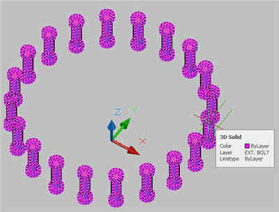
The 3D solid consists of multiple volumes.
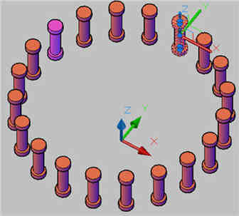
That solid after using SOLIDEDIT|SEPARATE command.
- It is recommended to avoid to do rounding, chamfering, holes and decorative elements if they are not important for the strength of design . They can complicate the construction of the finite element grid and increase the dimension of the problem (time to find a solution). But items which are bearing influence on strength of design, e.g., fillets, ribs, etc., can be presented in the model.
- The bodies, united in a block, are treated as one solid body which is obtained using a Boolean union of all bodies in the block. The bodies in the block may intersect with each other. No gap should exist between the bodies as this will generate an error of grid generation.
I have a study but I couldn't create FE mesh. What can I do?
You have constructed 3D model of your design, created a Study, and you are trying to create FE mesh, but you faill.
Why does it happen and how one can avoid it?
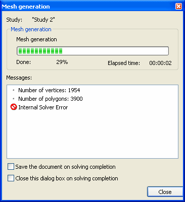
First, it is necessary to check the model according to the Requirements for 3D model.
Second, if the model has no intersections or gaps, but mesh is still not created, it is recommended to change mesh parameters which control the meshing process. In many cases changing parameters of meshing will provide success.
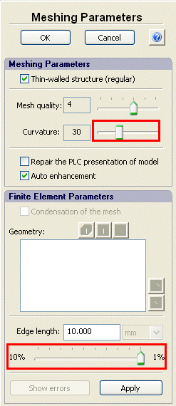
Meshing parameters.
The follows sequence of the varying meshing parameters varying can be put forward:
| 1. |
Adaptive/Regular - switch on/off. |
| 2. |
Curvature - improvement (larger than 8). |
| 3. |
Mesh quality - improvement (not disable). |
| 4. |
Edge length - decreasing or increasing. |
Unfortunately there are cases when creation of FE mesh is impossible despite changing the mesh parameters. Sometimes this happens because of an erroneous PLC model for the transfer of models from AutoCAD in Preprocessor of AutoFEM. This is the most difficult case, because for this there is not any solution via AutoFEM tools. In this case, it is necessary to modify the 3D model in AutoCAD in such a way as to eliminate errors in the creation of the PLC-model.
Our experience shows that if the mesh is not created, this usually means that a drawback presences in the model. This is especially true for assembly models.
If you cannot find the cause of which meshing failed, please contact with our Support Service (support@autofemsoft. com). Send us your model in .dwg with short description of the problem. We will try to help you.
Remember: meshing of strictly performed models usually is successful.
Should direct or iterative method be used for solving?
Generally, there are two main methods of equation systems solving. They are direct and iterative methods. The default mode of automatically choosing one of these methods is turned on in AutoFEM Analysis. If the number of equations is more than the number, specified in Processor settings (which equals 100,000 on default), the iterative method is used for solving. If the system is smaller, the direct method is used. You can set your own criterion for choosing a method of solving that is determined by parameters of your computer system. Also you can manually set whether the direct or iterative method should be used for solving the equation system, choosing the desirable mode directly before solving.
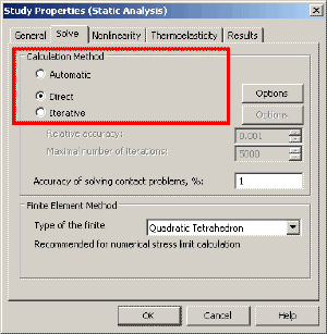
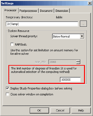
General recommendations of choosing and using these methods are as follows. The first criterion is power of your computer system. The iterative method has fewer requirements for the amount of memory (RAM) thanthe direct method. The next criteria are the quality of finite-element mesh and "thickness" of a problem.
The direct method is based on the Gauss method and its modifications. Full inversion of matrix occurs. This means that the large amount of memory is needed for storing the inverse matrix. In addition the time of calculation increases as N3 with number of equations N.
Usually the direct method works well and it is preferred when you have:
- relatively small equation system or a powerful computer system, based on x64-platform, and sufficient memory (RAM) amount (at least 4-8GB), which allows to place the inverse matrix fully in RAM. If you have such a computer system, you can efficiently solve problems up tol 1.5 -3 million degrees by the direct method in the "thin" 3D model.
- mesh has many "stretched" elements
- study has contact restrictions
The iterative method. The main advantage of iterative method is its posing ow demands on the RAM amount in comparison with the direct method. For the iterative method, the amount of necessary additional RAM is comparable with the amount of RAM for initial stiffness matrix location. Therefore, even relatively weak computer system (such as an office computer with Windows 32-bit operational system and no more than 3GB RAM) is able to solve up tol 1 million equations. But there is a certain drawback. Its performance depends on such property of tetrahedral finite elements as aspect ratio. When aspect ratio grows, the number of iterations increases and time of solving may significantly increase too. Therefore, if the mesh has many stretched elements (this often occurs if your model is slim and thin) or even "incorrect" ones, you may face the slowdown of the solving rate. Usually the iterative method works well and is preferred when you have:
- good mesh with total aspect ratio less than 8-4 and small number of stretched elements.
- "thick" model, meaning that you have several layers of tetrahedral elements per section.
- study has no contact restrictions.
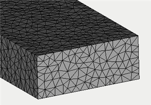
A "thick" finite element model. There are several layers of the finite elements. The Iterative method works better in comparison with the direct method in the medium and large models.
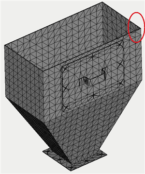
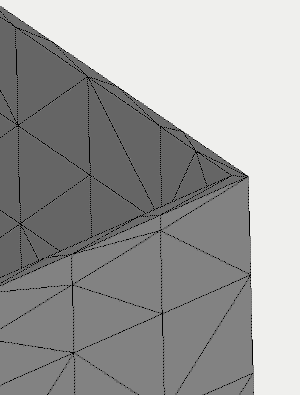
A "thin" finite element model. Mesh consists of one or two layers of finite elements. The direct method works well, and the iterative method may be down if quality of the mesh is poor.
How can I apply a force (or pressure) to a certain area of the part?
Often the loads are applied at some area of the part which you want to study. Use the AutoCAD's command IMPRINT to create an area of load applying on the facet of the 3D model. Firstly (before creating the study!), you shoud draw the geometry, which describes the area of loading, using AutoCAD's drawing commands. Then use IMPRINT to create a new facet on the existing face of the 3D model. See the screen-shots, illustrating these steps, below.
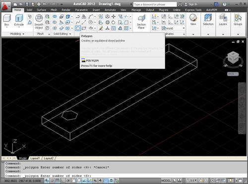
Drawing the contour of load aplying
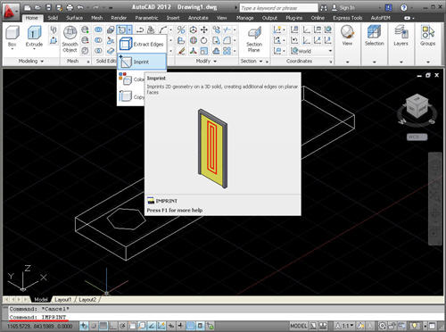
Use the command IMPRINT
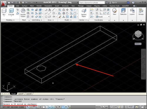
Selecting the body
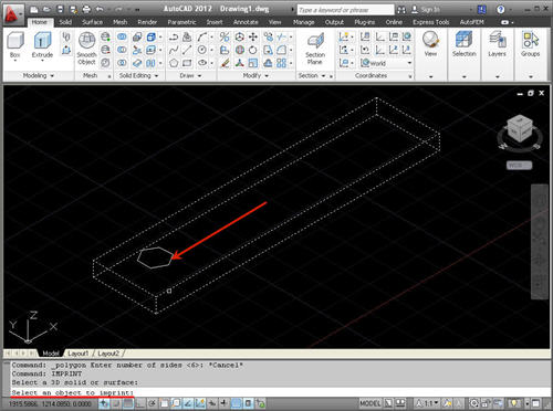
Selecting the contour
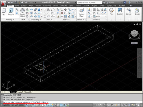
Deleting the contour
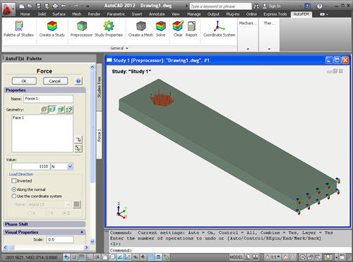
Creating the Study and applying the force


