New features of AutoFEM Analysis 1.4
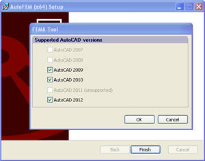
AutoCAD 2012 now is available. Support of AutoCAD 2012 is included starting from release of the 1.4 version of AutoFEM.
The Installer of AutoFEM Analysis is improved. A special tool is added to control the registration process, in which the AutoCAD version is to be installed in AutoFEM.
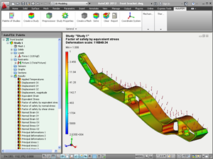
New folder "Examples" is added in the AutoFEM Group in the Windows menu “Start|All Programs”. This folder contains files with resolved AutoFEM Studies and allows for a quick understanding of the principles of AutoFEM Analysis by novices.
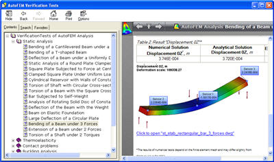
New verification tests are added to illustrate AutoFEM capabilities of studying systems which have no fixation and are equilibrated by forces or torques.
New features of AutoFEM Analysis 1.3
FEA Processor news
• A new type of the finite-element problem has come to the scene, being harmonic forced oscillations. This type of analysis allows for the calculation of amplitudes of the steady forced oscillations of a mechanical system, on which the harmonic compelling force acts, or at the displacement of the basis in accordance with the harmonic law. The result is amplitudes, accelerations, and overloads, using which may estimate the vibration strength of a structure within the set range of external impacts. This problem type is also available in the AutoFEM Lite version.
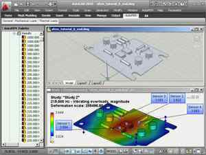
A new type of the finite-element problem: forced harmonic oscillations
• The opportunity is added to conduct static analysis for spatially non-fixed bodies, which become equable due to the forces applied. In the previous version of AutoFEM Analysis, to carry out static analysis, the structure was to be necessarily fixed in the space (attached). In the new version, the user may set a mode of “model stabilization” in space, if the original model is not sufficiently fixed.
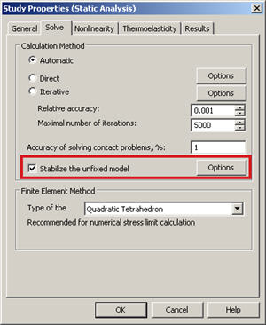
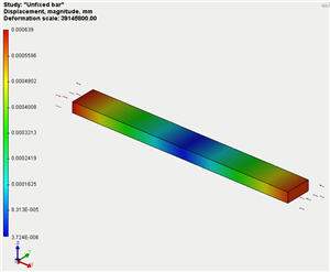
Calculation of unfixed model equable by forces
• A new type of result is added to the problem of statical analysis: the stress error estimation. This result type permits the estimation of a probability error when calculating the stresses. Most reliable results of the numerical work have a minimum spread of the integral error of the computed stresses.
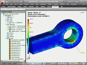
The Postprocessor window with the result of stress error estimation
• The new type of result is added to the problem of statical analysis: total strength of reaction. It allows one to assess the estimated value of reaction forces, emerging in the structure’s support.
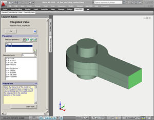
Calculation of reaction forces
• The algorithm of non-linear static analysis (large deformations, geometrical non-linearity) has been improved. Now we have a possibility to solve problems involving general restrictions (Version 1.2 permitted solely "fully fixed" restrictions).
Meshing news
• The algorithm of the work of the generator of finite-element meshs with assemblies has been improved. In particular, the drawback of an earlier algorithm was corrected, including the creation, at assembly structures, of an excessive amount of finite elements that unjustifiably enhanced the dimensionality of the finite-element problem. A new generation mode is a default setting.

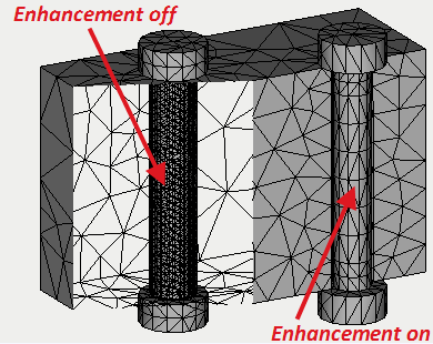
Preprocessor news
New types of boundary conditions appeared
• Additional Mass. This command is used only with the load "Acceleration". It allows for a definition, in the system, of additional inert loads coming from a certain massive element of the structure, for instance, as a result of gravitation. We assume thereat that we are not interested in the strained behavior of the massive element per se, but it is necessary to account for its action on other parts of the system. The dimensionality of the problem solved (the number of equations) can be significantly reduced thereat. The Additional Mass can be used in the following studies: static, frequency, and stability analysis, and analysis of forced oscillations.
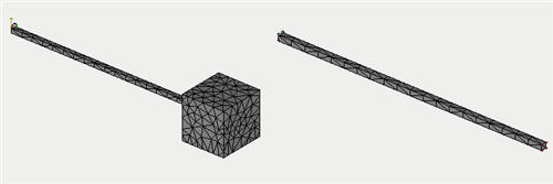
Using command “Additional mass” for decreasing the problem’s dimensionality
• Elastic base. This type of restraint allows one to define the elastic interaction at the body’s boundary. The elastic base is used to model the touch of the body with the external elastic medium which is deformed together with the body. For instance, the building foundation and the building per se are deformed altogether with the earth on which it stands. Other examples of the body connected with the elastic medium are the dam, railway, etc.
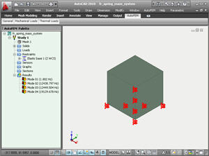
Depiction of the elastic support in the AutoFEM Preprocessor
• Imaging of boundary conditions in the tree of studies has been perfected. Now the value of the applied load is reflected directly in the tree of studies. This essentially eases the perception of conditions of the finite-element problem.
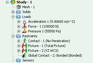
Boundary conditions parameters are reflected in the tree of studies
• Exclusion of the boundary condition from the calculation. A new convenient possibility is added to temporarily exclude any boundary condition (force, restraint, etc.) from the calculation, not removing it in fact The excluded boundary condition is marked by a gray icon in the tree.
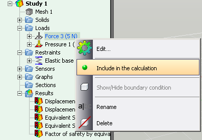
Temporary exclusion of the boundary condition from the calculation
• Command “Hide the body” has been updated, which allows one to temporarily hide the body in the Preprocessor window. Now the hidden body is marked by a special icon in the tree of studies. Also, the action of the command applies to all windows of Pre and Postprocessors in AutoFEM.
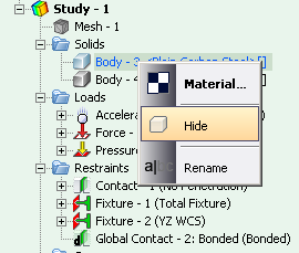
Retrieval of the command to hide the visibility of the body
• The commands’ interface has been updated. All commands retrieved from the AutoFEM palette now have unfolded bookmarks allowing for space-saving at the display, as well as interactive tip, showing the algorithm of the current command (in the language of the system’s interface). This ensures fast learning of green users.
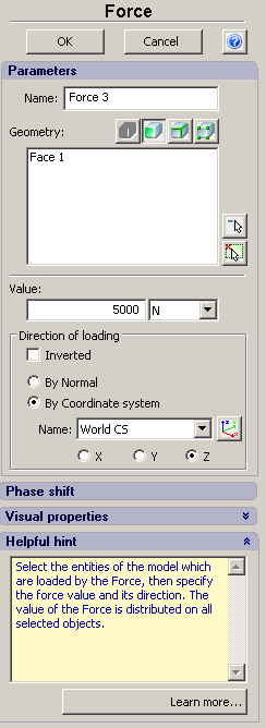
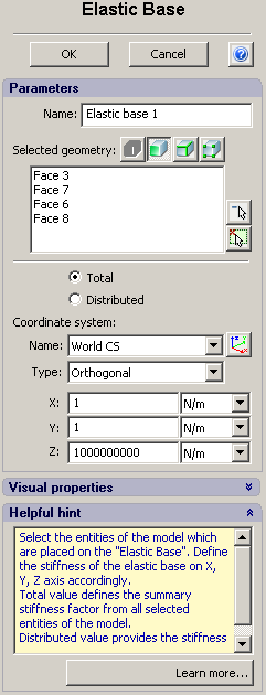
The new interface of AutoFEM commands
Postprocessor news
• Sensor. A new object has been added for measuring of the result value at the defined point of the finite-element or 3D model. Now every user can define any number of the sensors and use them for analyzing of the results. The sensors are saved in the file .dwg. The sensor can has a multiline commentary which is also saved in the file and which is displayed in the Report of the FEA problem.
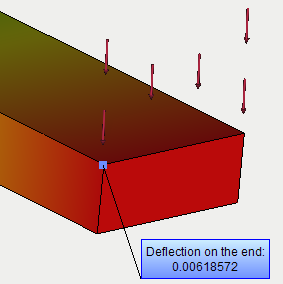
Using the sensor for indication of the result value
• Graph. The new type of result is Graph. Using a set of sensors, you can construct the graph of the changing result in the function of dependence across sensors. Besides, the graph for the multiple results can be constructed (for instance, amplitude-frequency characteristic).
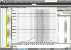
The graph of amplitude-frequency characteristic
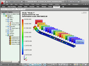
The set of sensors for measuring the result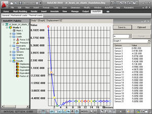
Graph constructed using the sensors’ data
• A new convenient tool is added to regulate the model’s orientation in the windows of Preprocessor and Postprocessor. From the context menu in the window of Pre-Postprocessor, the user may select the desirable orientation of the model (similarly to AutoCAD views).
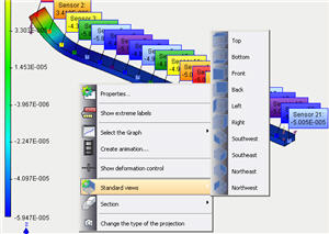
The command for fast control over the model orientation
• The command to construct sections of the model was reworked. Now, you are able to retrieve the command to precisely position the section’s center and orient the plane of the section in space.
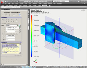
Using the command for precise positioning of the section’s plane
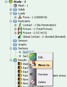
• Saving the section’s orientation. The configuration of the section can be saved to ensure the fast access to the set orientation of the section’s planes.
 .
.
Verification Tests news
• The number of verification examples illustrating the exactness of problem solutions was increased twice. Verification problems are now grouped by analysis type that allows for an easy finding of the example using the respective problem class.
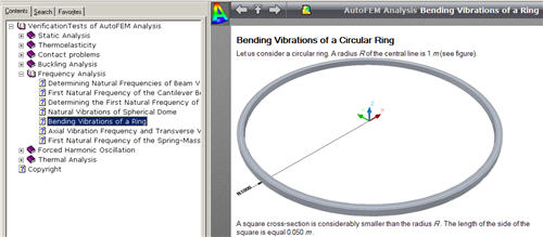
Tutorial news
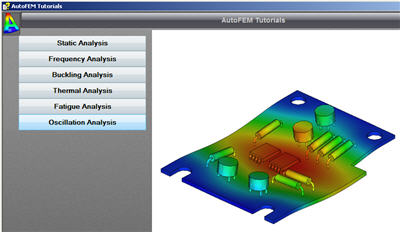
A new lesson aimed at working with module “Forced Harmonic Oscillations” was added.
