
New Features of AutoFEM Analysis 3.1
Support of AutoCAD 2019 and ShipConstructor 2019
AutoFEM Analysis 3.1 supports operation with AutoCAD x64 versions 2010, 2012-2019 and ShipConstructor 2019.
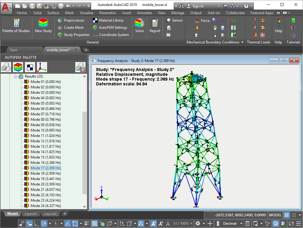 AutoFEM 3.1 supports AutoCAD 2019 and ShipConstructor 2019
Improved dialogue of result configuration
As you know, in AutoFEM 3.x, the user should configure the list of calculated and stored results before starting the calculation. In version 3.1, this dialogue is modified and allows you to simultaneously select the calculated result and determine its visibility in the AutoFEM Palette.The estimation of the volume of the saved results and the adjustment of the results by default are also improved.
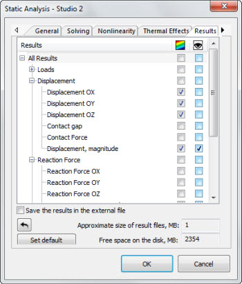
New dialogue of result adjustment
Graph of extremums for dynamic analysis
There is a new opportunity to generate a graph of extremes of multiple results.Useful for dynamic studies including force oscillations.This functionality allows anyone to automatically find the maximum value of a result at each time or frequency step and therefore see when the result takes extreme values.Next, you can open the result at this time or frequency step and examine it in more detail.
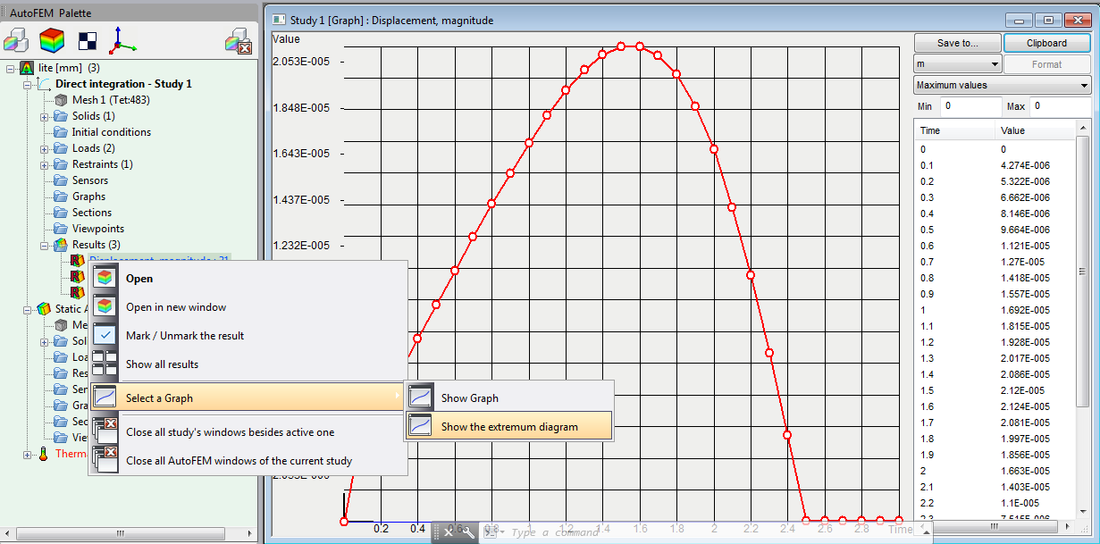
Graph of extremums
Improved dialogue "Deformed state"
In the dialogue of time and deformed state management, the option to automatically update the extremum labels in the Postprocessor window is added.
 Updating extremums in Postprocessor window
A lot of other improvements of the software have been implemented.
It is recommended to update your installation of the software to the current version AutoFEM Analysis 3.1.
New Features of AutoFEM Analysis 3.0
Supporting AutoCAD 2018
AutoFEM 3.0 is compatible with AutoCAD 2018. Starting from version 3.0 AutoFEM Analysis is supplied only with capacity of x64, i.e. now it is necessary to use AutoCAD x64 to operate the system. Therefore, support of AutoCAD 2007 -2009 has been terminated as they were supplied mainly in 32-bit version. So, the AutoFEM Analysis 3.0 supports operation with AutoCAD x64 versions 2010, 2012-2018.
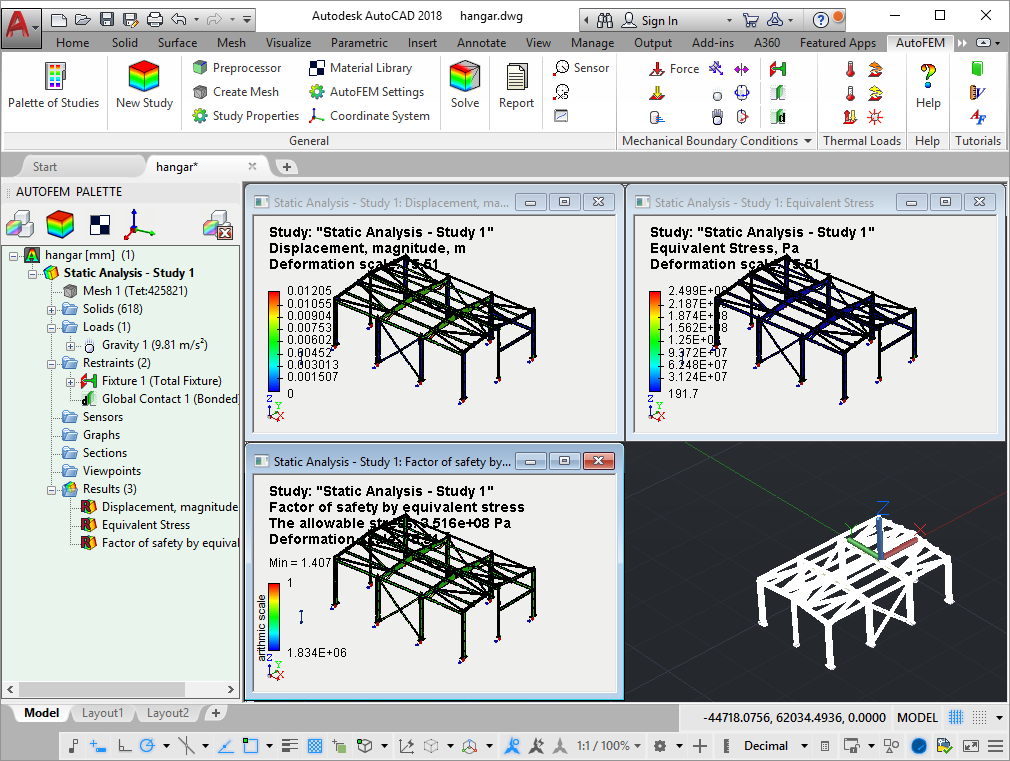
AutoFEM 3.0 supports AutoCAD 2018
Supporting ShipConstructor 2018
AutoFEM 3.0 supports integration with ShipConstructor 2015R1-2018R2. The opportunity to choose material library AutoFEM has become available in the integration dialogue, the system will obtain physical properties of materials from this library.
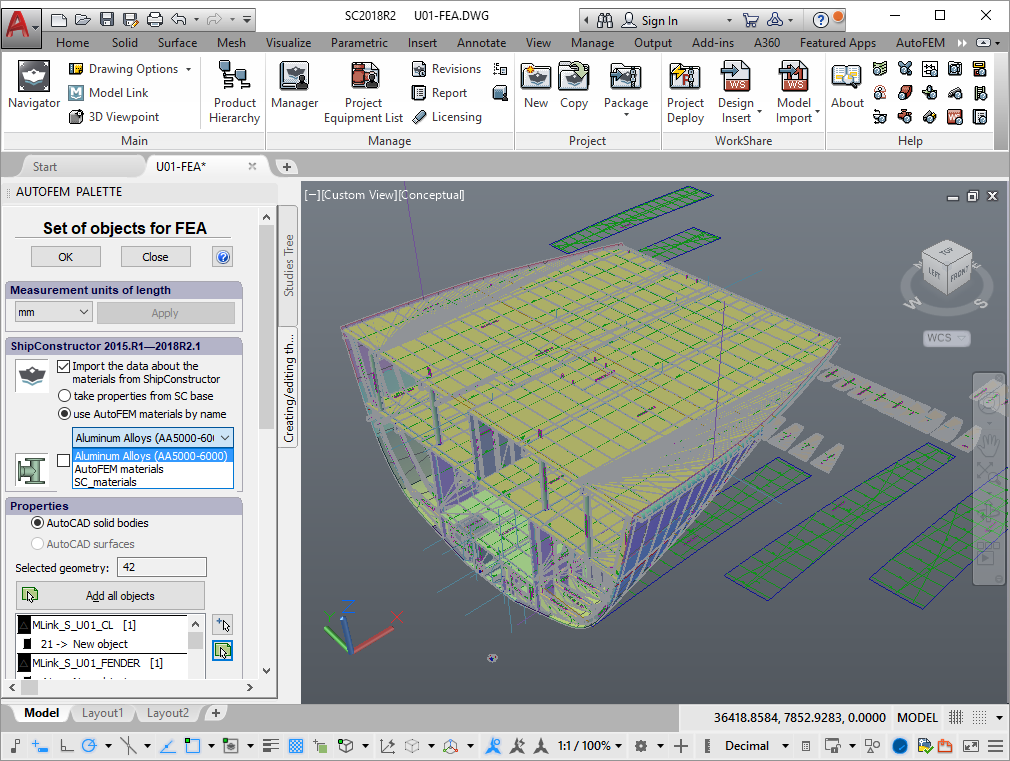
Opportunity to choose material library for work with ShipConstructor
New AutoFEM Launcher
The system has obtained a new tool for the application launch and work with the accompanying materials. AutoFEM 3.0 Launcher enables the launch of the system from a common interface, implementation of necessary language settings and license settings, obtaining access to files and accompanying materials such as help, lessons and verification patterns.
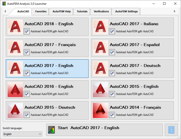
New AutoFEM Launcher
New computational capabilities
Computational capabilities of the system have been significantly expanded in version 3 AutoFEM Analysis. In particular, a new type of study has been added – Dynamic analysis. Dynamic analysis provides for the ability to model the behaviour of the system under the effects of time-varying environments (forces, displacements) and significantly extends the range of the system application.
New type of study - "Dynamic analysis"
Three options for solving dynamic studies have been implemented which differ in the method of creation and solution of studies. Dynamic analysis permits one to model the behaviour of a structure (including movables) under the effect of time-varying forces and moving bases (fixations). Solution of the dynamic studies are made successively at a specified time slot with a determined time step, i.e. there are results from the system, a “snapshot” at every time step. Thus, the volume of the obtained results can be very large. Three options for the studies of the dynamic analysis are available in AutoFEM Analysis.
Dynamics - Direct Integration
A total system of algebraic equations which are comparable with a similar statistical strength study in the sense of solution complexity, is solved in this type of dynamic study at each time step. The advantage of this method is found in its accuracy and the ability to use it in nonlinear problems. However, usage of the method for long time processes can be difficult because it’s time consumption can be unreasonably high.
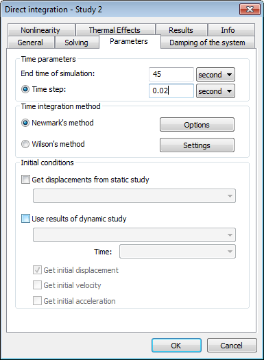
Dialogue of dynamic analysis solver settings
Dynamics - Mode Superposition (Linear dynamics)
This type of study requires the availability of a calculated problem of frequency analysis. The dynamic study solution is presented in a mode-superposition method as a combination (sum) of previously calculated forms of system oscillations. Such a type of study requires preliminary solution of a frequency analysis problem in order to find Eigen forms (modes), of the system under study that can be unprofitable enough from the perspective of computation. However, if Eigen frequencies and modes are known, finding of a dynamic study solution will be very quick and efficient from the perspective of the required computational resources. That is why this method can be recommended for modeling relatively long processes with a great number of time steps.
Dynamics - Frequency & Mode Superposition
Mode-superposition method integrated with the solution of a frequency problem. A study can be created with no frequency problems in a document because such problems will be solved automatically before the launch of solution of a dynamic study.
Lifting and transporting operation of a vessel unit
As a result of this solution of the dynamic studies, we obtain a complete picture of the system’s behaviour – displacement, speed and stress in the system at any one time at the specified time slot.
Consideration of temperature dependences of material properties in mechanic and thermal studies
The ability to consider the impact of temperatures on construction material properties is added to mechanical and thermal studies. This permits one to evaluate more precisely strength and behaviour of the structure operated in an irregular temperature field.
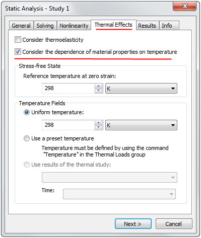
Mode of consideration of dependences of material properties on temperature
during calculation is activated on the Thermal Effects tab.
Improvements in the thermal analysis module
Radiant heat exchange with re-reflections
Algorithms of calculation of radiant heat exchange have been improved, particularly, the ability to consider reciprocal re-reflections between bodies during heat exchange has been added.
Radiant heat exchange with re-reflections
Consideration of dependences of materials and boundary conditions on temperatures
The ability to consider the impact of temperatures of thermal boundary conditions (nonlinear heat problems) has been added. Temperature dependences are set in the form of graphs in boundary conditions dialogues.

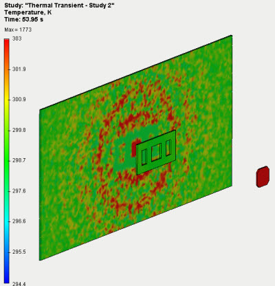
New calculation mode "Until temperature equilibrium"
The ability to launch a transient thermal analysis with indefinite end time has been added. This calculation is performed until a fixation of temperatures (until they stop changing) and enables the determination of an estimated time of thermal equilibrium attaining as is used for the solution of studies of radiant heat exchange with re-reflections.
Settings of transient thermal process
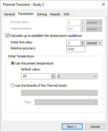
Changes of dialogue "Set of Objects for FEA"
A special-purpose button in the section "Measurement units of length" permits one to change the length of measure units of a model without reconfiguring a set of bodies.
Revised dialogue of the command "Set of Objects for FEA"
Change of run of the command "New study"
In connection with the increase in types of studies supported by the system, the command New Study obtained an additional dialogue for selecting a type of study. Available studies are arranged into three groups: Stationary, Dynamic and Thermal studies. After having called a command, the user should select the desired type of study after which the respective dialogue will be opened for the addition of bodies to the study and setting of other parameters.

New dialogue of the study type selection
New functionalities of the selector. New selection tools
The ability to select objects in the Preprocessor window by means of a frame has been added in all commands using geometry selection included in the New Study command. Two types of frames are available –arbitrary shape and rectangular.

Selection of the load application area by means of a frame "Lasso"
Study copying command is improved
The ability to assign a name to the created duplicate of the original study in the course of copying has been added as well as being able to copy a study together with the results, where necessary. Names of boundary conditions of the original study are also saved in the copy.

Change of run of the command "Solve"
The general order of a calculation launch has been slightly changed. After setting of main options of a calculation, an additional dialogue appears in which the user is offered the opportunity to mark the results that should be saved. The system also displays an approximate volume of saved results (in MB) and available free space on the disk at that moment. This dialogue is especially useful in dynamic studies to which a large volume of generated data is specific.
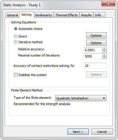
First step - Static solver settings
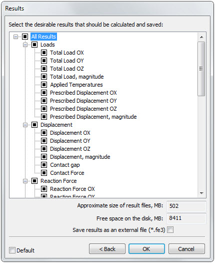
Second step - dialogue of setting of the results to be saved
Improvements of the studies on the basis of surface models (calculation of shells and plates)
Significant improvements have been implemented in the study creation dialogue for calculation by means of plate finite elements.
Flip of a normal to the surface
A special command for flipping a normal of the selected facets has been added to the dialogue of creating Shell study.
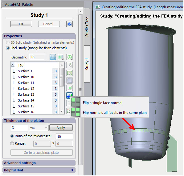
Command for flipping normals in the dialogue of creating shell study
The number of the results available for analysis has been increased
The number of the obtained calculation results has been increased for the shell studies.
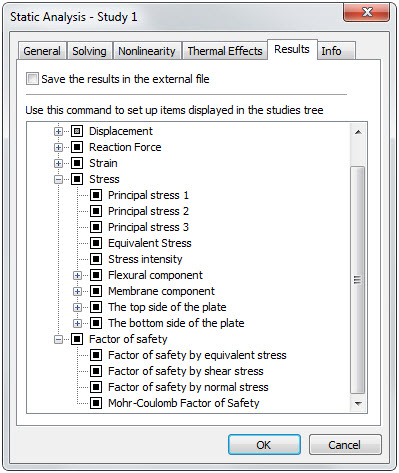
New results are available for plate studies
Material library
Functionality of the material library has been significantly extended.
Graphs of temperature dependences of material properties
It is known that the properties of all materials depend on temperature. Now it has become possible for the user to assign a graph for any material parameter which displays dependence of such parameter on temperature. Accordingly, the system takes into consideration this dependence during calculation.
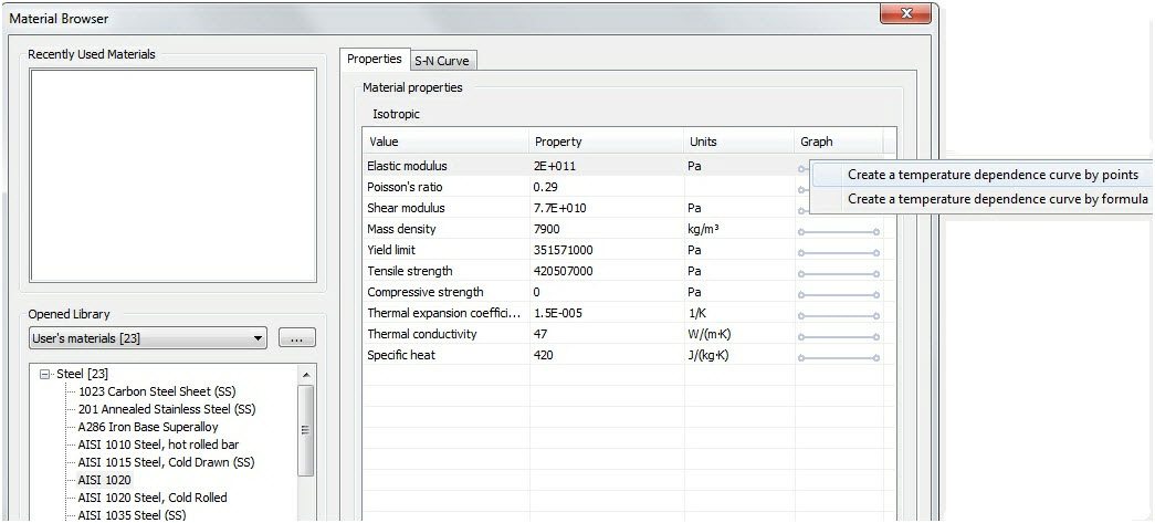
Temperature dependence curve can be created for every material parameter
Materials export-import
The ability to export materials to an external file in table format *.csv has been added as well as being able to import data from the same format. This facilitates significantly the addition of new data, concerning materials, to the library. The user can prepare a table containing materials data in an independent table editor (MS Excel, LibreOffice Calc, etc.) and then upload them to AutoFEM library.
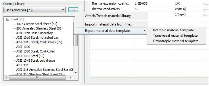
Commands of the materials export-import
Increased the total number of materials in the library
The quantity of materials supplied with the system has significantly increased. The total number of available structural materials now exceeds 1 thousand.
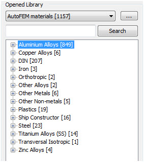
Available materials in the material library
Searching for materials
Now it has became possible to search for a material by its name.
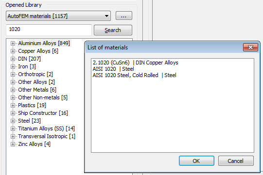
Search for a material by name
Graphic editor
The ability to create customized graphs has been added to the system, these graphs can be used to assign temperature dependences of the material properties as well as during the assignment of time-varying or temperature-dependent boundary conditions.
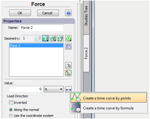
Call of the graph creation command in the boundary condition dialogue
The user can create two types of graphs of kind Y(X):
1) Graph determined by values of the function in the assigned points ("Point-to-point graph");
2) Graph assigned by a continuous function ("Graph by formula").
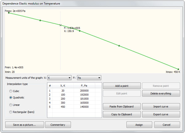
Point-to-point graph of temperature dependence of the elastic modulus
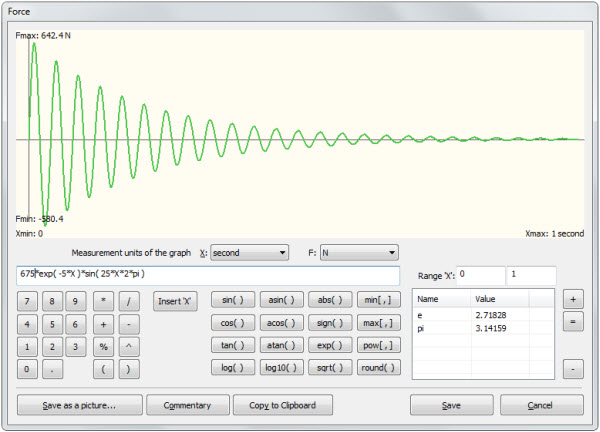
Graph of temporal variation of force assigned by the function
Graphs can be exported, imported, saved as pictures, used in reports, etc.
New options of Mesh Generator
Tetrahedral Mesh Generator
Stability of the tetrahedral mesh generator when working with large assembled 3D models has been significantly increased. A mode of successive part-by-part meshing of the assembly components has been added. It makes it possible to generate a tetrahedral computational mesh for assemblies comprising many thousands of parts.

Model comprising 1417 parts in AutoFEM window
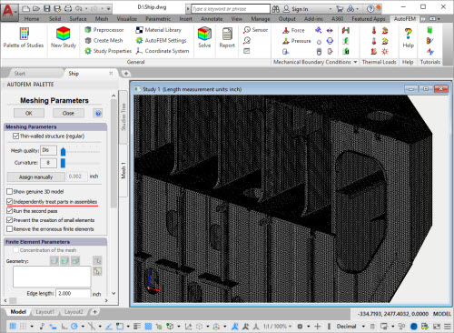
New option of the mesh generator facilitates construction of tetrahedral meshes of large assembled models
Surface Mesh Generator
Triangle surface mesh generator has been added which is independent of AutoCAD. This generator provides for a better quality of breakdown of the surface of plane parts.
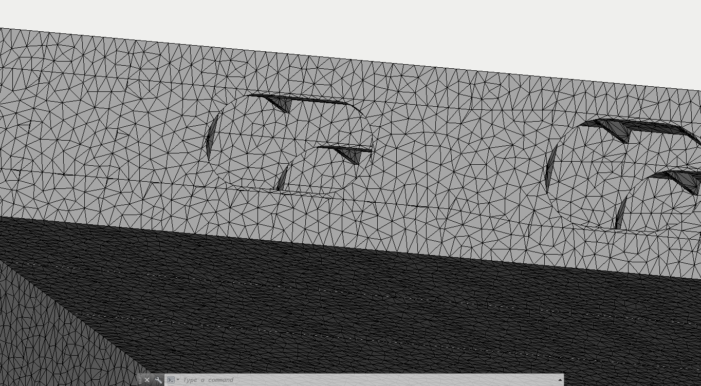
Better quality of generation of triangle finite-element meshes
New modes of the command "Diagnostics of Study"
Additional options have been added to the "Diagnostics of Study" command.
Displaying solids without mesh
The diagnostics mode shows a list of solidswithout finite-element mesh and their total quantity. There is a special button "Move to another document" which transfer the 3D model into the new independent AutoCAD document where user is able to scrutinise the structure and to correct it.
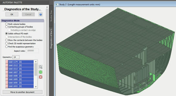
The system has found 14 solids without mesh - marked light green colour
Moving to another document
In several diagnostics modes (such as "Non contacting bodies" and "Solids without FE mesh") the user is able to transfer 3D model into another .DWG document. The new document will comprise the whole original 3D model, but each object listed on the geometry list will be placed on its own layer. Consequently, the user can then control the visibility of parts and analyse their geometry for errors.
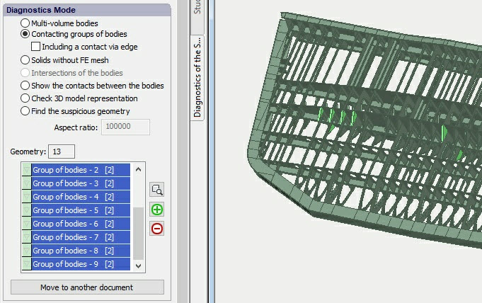
The button "Move to another document" is active for certain diagnostics modes.
Non contacting parts are marked with light green colour.
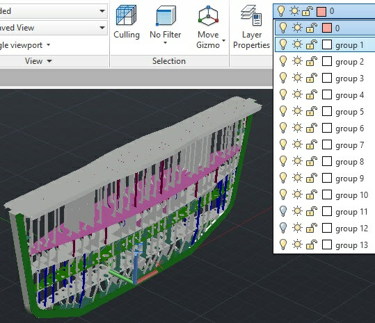
The system creates layers for each object on the list
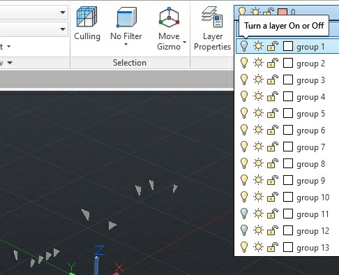
User is able to hide some parts to reveal failed parts and then analyse them
New command Gravity
The command for assigning gravity has been taken out the dialogue of the command Acceleration to a separate dialogue for the users' convenience. The command Gravity applies automatically the set value of the acceleration of free fall to all objects selected for study and is displayed in the Postprocessor window as one icon close to the model. Only one Gravity can be determined in the study.
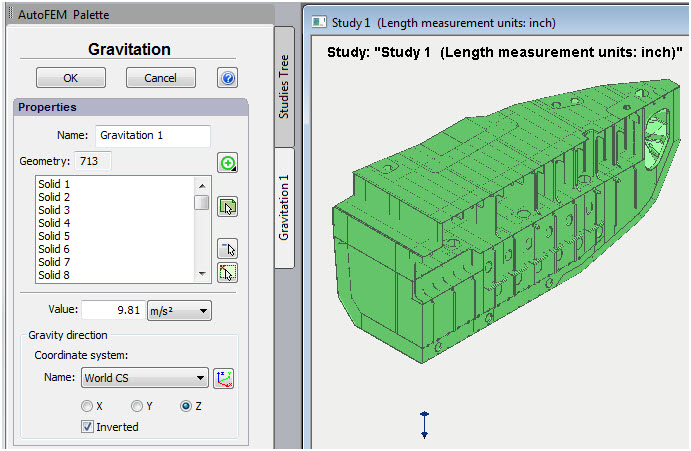
Gravity assignment is taken out as a separate command
Remote loads
Three new commands for the assignment of so called "Remote loads" have been added.
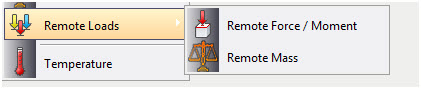
Remote loads
Remote force, moment
The command permits one to assign force action on a structure from any external object for which it is unreasonable (or impossible) for whatever reason to be included directly in the study. A classic example is the assessment of the resistance of a ship’s mast foundation to the wind load. In which case, an integral (aggregate) value of wind load and centre of application thereof is assigned.
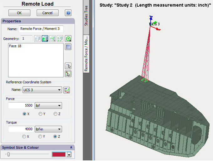
Remote force/moment assignment command
Remote mass
The command permits transmission of mass-and-inertia effects of a structural member to the system without creating finite-element mesh and a model for such elements. For example, to transmit mass-and-inertia effects of an electric motor to a load-carrying structure. It is evident that if a problem is set to assess strength or dynamics of a load-carrying structure (bracket support), it is not reasonable nor always possible to construct a full-featured finite-element model of such a complex device as an electric motor. In this case, for the purpose of calculation it is enough to determine the location of a centre of mass and the relevant mass-and-inertia parameters of the electric motor which will impact on the load-carrying structure.
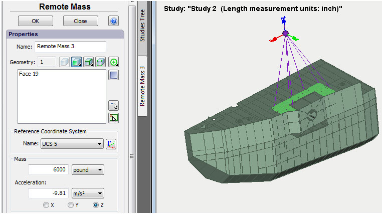
Remote mass assignment command
Remote displacement
Remote displacement permits one to transmit the effects of a known displacement of any remote structural member to the system, this member being connected to the structure by rigid connection.
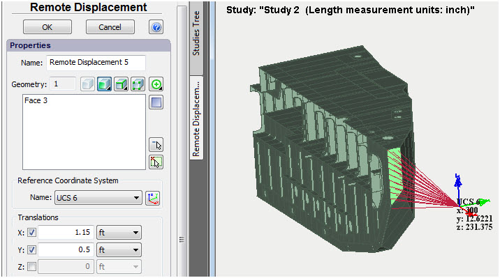
Remote displacement assignment command
New command "Measure the model"
In the course of the analysis of structures, the necessity often arises to assess quickly mass-dimensional parameters of the modelled system. New command "Measure the model" permits one to take basic measurements of the structures. The command has three modes and permits one to take the following types of measurements:
• Geometric measurements - volumes and weight of bodies, surface area, length of ribs.
• Distance between two points of the model
• Distance from a point to geometry (ribs, facets)
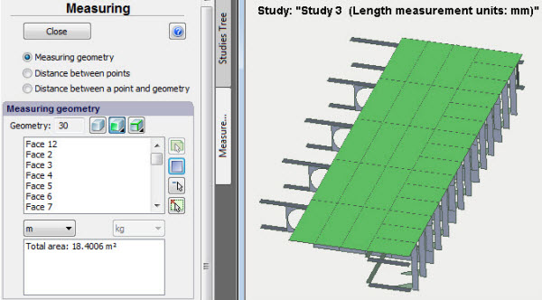
Surface area measurement
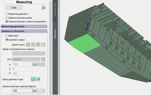
Distance from a point to geometry (facet)
Improvements of the command Hydrostatic Pressure
Visual display of the assigned liquid level (semi-transparent circle in the middle of the coordinate system determining the liquid level) has been added to the command Hydrostatic pressure. Furthermore, the arrows showing direction of the pressure application have now different sizes depending on the depth which facilitates visual check of accuracy of the load application.
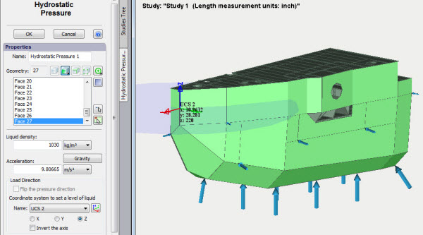
Better visualization of usage of the command "Hydrostatic pressure"
Improvements in the command Coordinate System
The ability to display names and numeric values of the coordinates of the center in the Pre-Post-processor window has been added to the user coordinate systems.
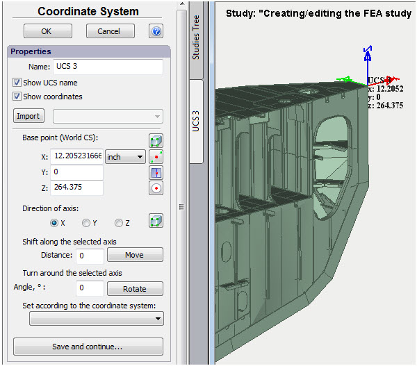
Name and coordinates of the user coordinate system can be displayed in the Preprocessor window
Improvements in the commands Sensor and Group of Sensors
The ability to bind to the geometry elements has been added to the commands of creation of sensors and group of sensors which facilitates significantly the usage thereof.
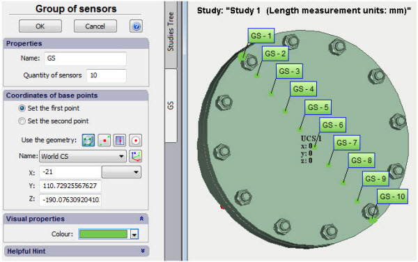
Geometry elements can be used for sensor positioning
Saving of Viewpoints and Sections
The ability to save the current orientation of the model in the Pre-Post-processor window has been added in order to have subsequently instant access to the saved orientation. The command is accessible from the context menu, and saved viewpoints and sections are displayed in the respective folders in the studies tree.
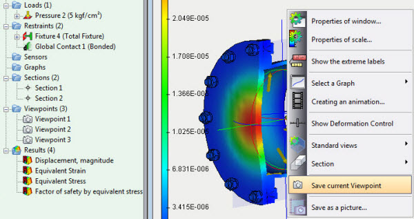
Context menu command of viewpoints saving
Import of sensors and sections
A command of import of sensors, viewpoints and sections from one study to another has been added.
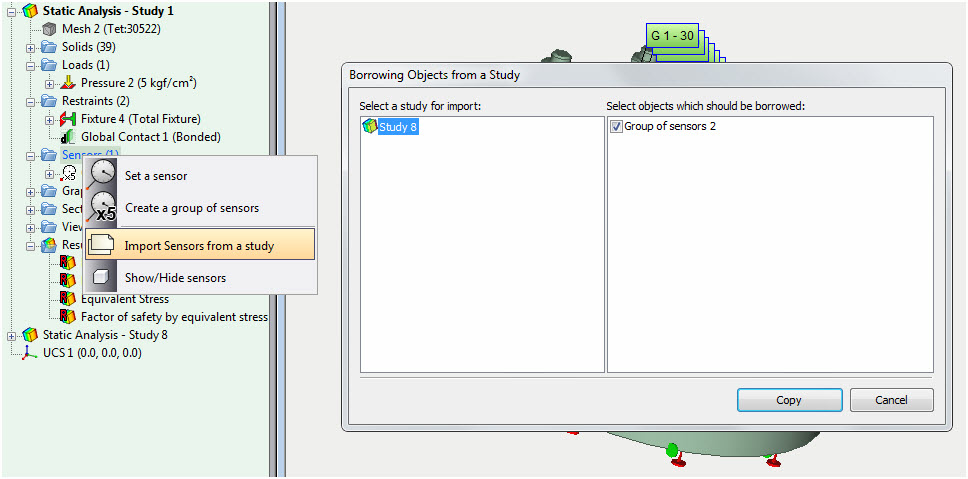
Copying sensors, viewpoints, sections from another study
Working with result windows
In the context menu in the study tree, convenient options for working with result windows are added.
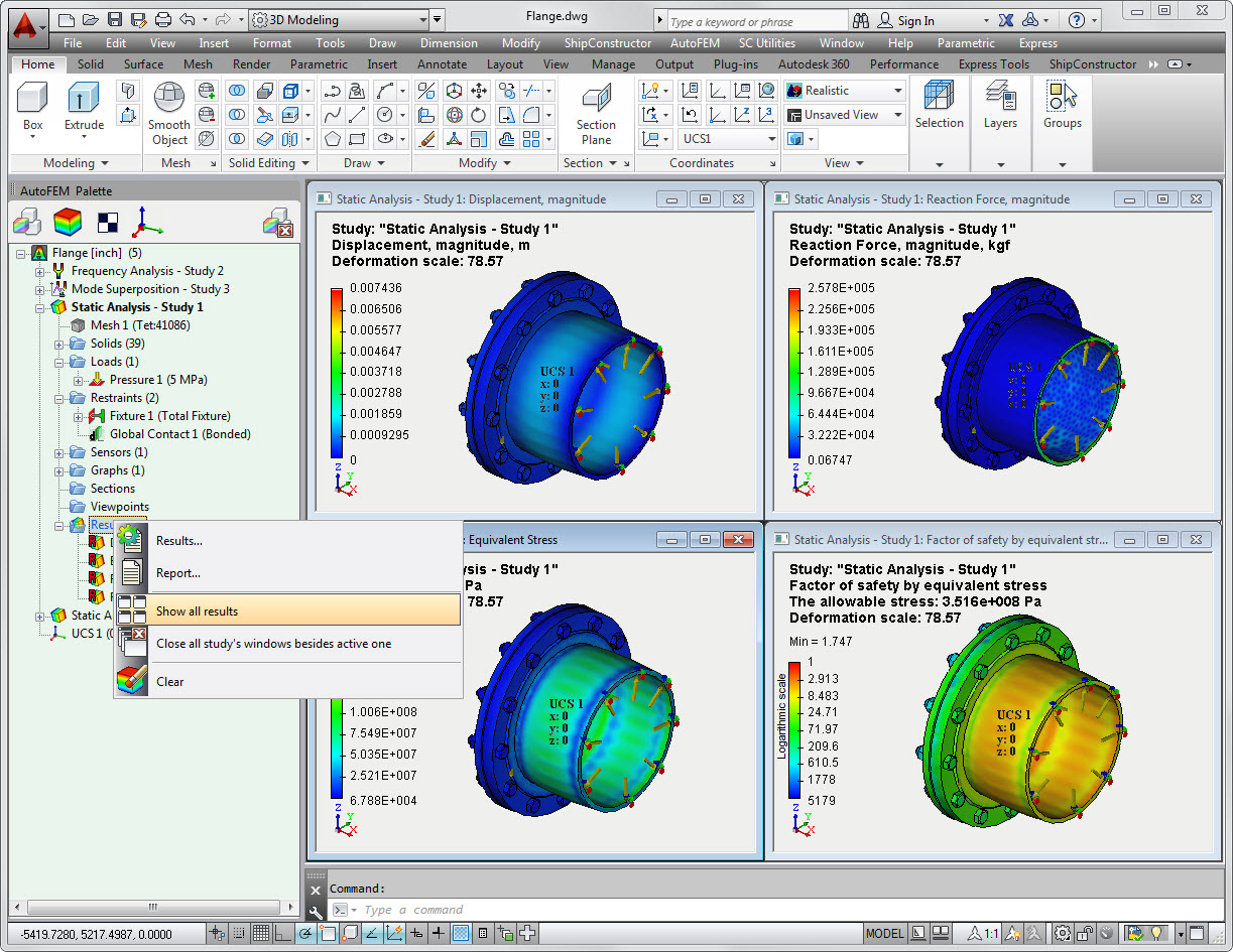
Show all results
The command opens all the results of the current study, each in its own window, and evenly places them on the screen.
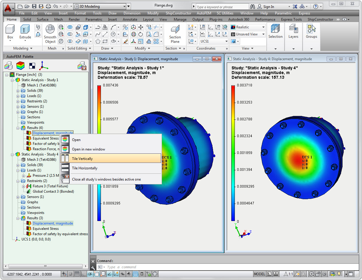
Comparison of results
The "Tile Vertically / Horizontally" command allows you to open several windows selected with the Ctrl key held down, placing them in the window with a "tile", which allows you to visually compare the diagrams with each other. The results may belong to different studies.
Switch between Postprocessor windows
A group of special commands in the context menu on the active study and on the Results folder allows you to easily switch between the open result windows and automatically close them.
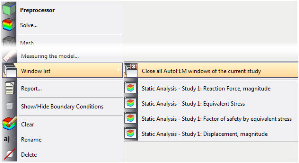
Commands for controlling the visibility of Postprocessor windows
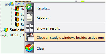
Closing all AutoFEM's windows
Saving of a diagram as a picture
The ability to save a picture in a file or to copy it to Windows clipboard has been added to the Pre-Postprocessor window.
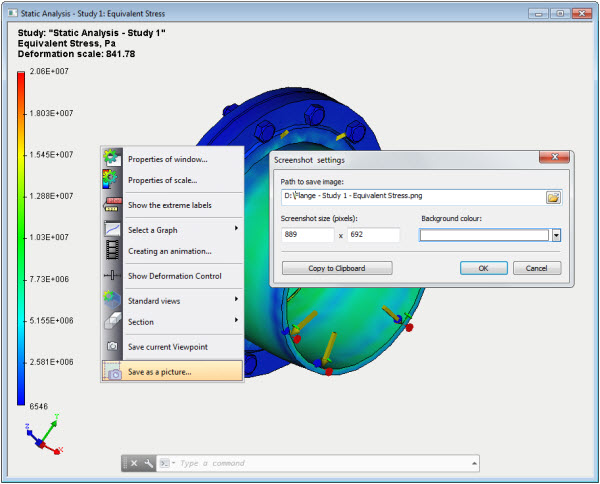
Creation of a picture from the content of the Postprocessor window
New changes in the Reports
Default views
Revised dialogue of report generation permits to set view orientation which is used in the report for default image generation (for unopened results).
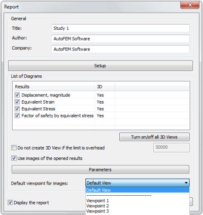
Revised dialogue of report generator
New visualization of 3D models in the reports
A 3D model of the result in HTML-report is now shown in a separate browser window opening automatically, the transition to which is made through 3D View hyperlink on a two-dimensional diagram of the result. Performance of 3D model visualiser has been significantly improved. Installation of third-party applications is not required.
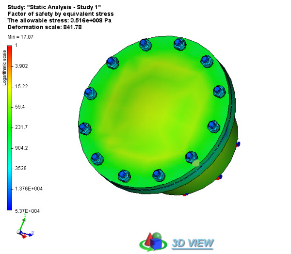
New 3D views in reports