New features of AutoFEM Analysis 1.7
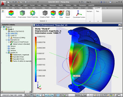
Support of a new version of AutoCAD - AutoCAD 2013
Starting from Version 1.7, AutoFEM Analysis supports work with six versions of AutoCAD, namely AutoCAD 2007, 2008, 2009, 2010, 2012, and 2013.
New possibilities of the Preprocessor
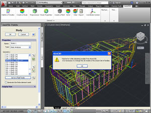
Localization of erroneously created bodies. The new functionality is added to find errors appearing when studies are created. Sometimes, at complex models consisting of hundreds of objects, errors related to geometry translation to the Preprocessor of AutoFEM Analysis appear. Now, when the system manages to localize such error, it produces the diagnostic message and switches to the regime of editing the study. Erroneously created bodies are marked in the list of studied bodies with the term #ERR# and the button of rolling through problematic objects becomes active. The user can exclude the erroneous body from the study or correct it using AutoCAD and re-create the study.
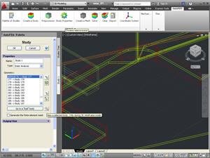
Transition to the selected body. In the command “Create a Study”, the special button appears which permits to make closer to the observer the body selected from the list of the problem composition. The button functions in the mode of imaging the 3D model (it does not work in the mode 2D Wireframe).
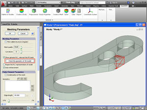
Testing the PLC-representation. In the command designed for mesh creation, as well in the command Study Diagnosis, the new function appears, allowing for the search of errors of representation of the 3D model in the AutoFEM Preprocessor. This command is needed when the finite-element mesh cannot be constructed for unknown reasons.
The command shows “suspicious” elements of the model, which may have errors of geometry. If the change of meshing parameters (the size of finite elements or curvature) fails to eliminate the problem, it can be assumed that the AutoCAD 3D model has inaccuracies of geometric presentation. In this case, the user must return to the AutoCAD window, analyze the “suspicious” item and try to eliminate the problem using AutoCAD means.
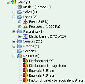
Additional information in the tree of studies. Now, the tree of study reflects the number of elements in the finite-element mesh. In addition, opposite to each folder of objects, the number of objects it contains is shown.
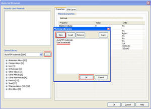
Applying the user’s libraries of materials. Starting from Version 1.7, the system library of materials in AutoFEM Analysis becomes inaccessible for modification by the user. New materials may be created by the user only in the user’s library created by him/her.
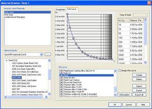
The new editing program for graphs of SN-curves. The imaging and editing of SN-curves in the editing program for materials is improved.
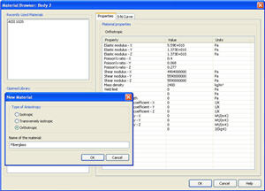
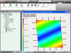
The editing program for orthotropic materials. Functionality of the incorporated editing program for materials is expanded. Now it is possible to set up materials with non-uniform physical parameters (orthotropic and transversally isotropic materials).
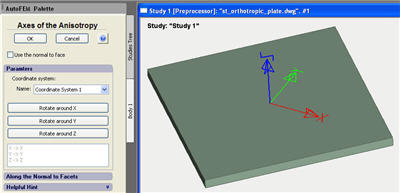
New command Anisotropy Axes. To set up orientation of elasticity axes of anisotropic materials, the special command is added, which is accessible from the context menu located in the study tree.
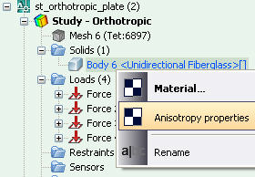
Using a special dialog, one should select the local coordinate system, whose axes coincide with orientation of main elasticity axes of the orthotropic material.
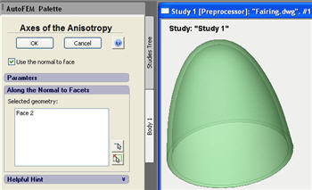
For the transversally isotropic bodies, there is an option to set up the anisotropy parameters based on the body’s geometry. To do this, in the command for setting the axes of anisotropy, the user must choose regime "Use the normal to face" and select facets, the normal to which will set the direction E'=Ez. This method permits to define the parameters of the transversally isotropic material for bodies of the complex spatial configuration, including curved forms (e.g., curved pipes and cones).
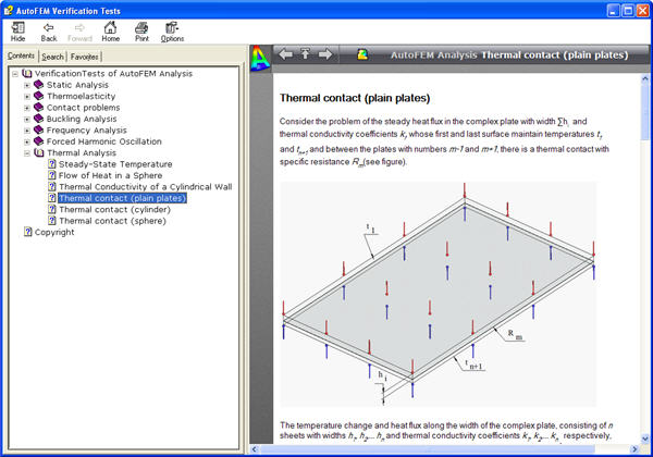
New boundary condition “Thermal contact”. The phenomenon of thermal contact emerges because of roughness of contact surfaces at the boundary between two bodies, when microscopic gaps are formed, which are filled with air or another surrounding medium. This medium has heat conductivity coefficients which differ from the contacting solid bodies. As a result, a spasmodic change in the uninterrupted temperature field occurs at the border of the contacting bodies, which is typically caused by worse conditions of heat energy conductivity at this border. This physical phenomenon is called the thermal, or heat resistance. Now AutoFEM Analysis has a special command permitting to set a priori known values of thermal resistance and account for its influence on the transfer of thermal energy.
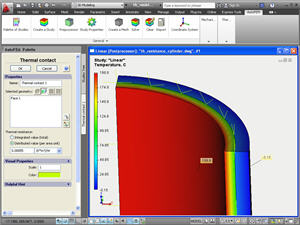
A new command “Thermal contact”
New possibilities of the Processor
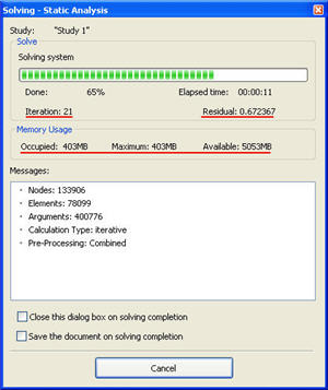
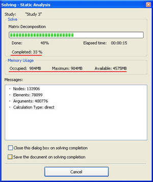
New static solver. The rate of solving static analysis problems is significantly increased. Acceleration is by 3-5 times on average for the iteration method. Besides, now in the process of calculations, the user has the opportunity to accurately control the entire process of solving systems of equations, since additional information is now in the dialog. For the iteration solver, the number of the current iteration and the residual error of the solution are presented. For the direct method, the percentage of the total number of the solved equations is shown. The user can see in the real-time mode, what is the rate of solving equations, and manage this process. In addition, for both solving methods, three parameters are shown, which characterize the need in operational memory: what amount of memory is occupied by the solver at present; maximum usage; and how much free operational memory is available in the system just now. These parameters allow each user to assess whether his/her computer system fits the solution of a particular problem.
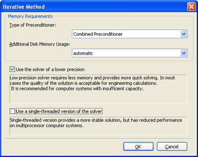
Solving systems of equations with lower precision. In the static solver, the option of launching the low-precision solver is added. This mode consumes nearly by a third lower amount of operational memory and, besides, calculations go faster. In most cases, the precision of solving equations which is sufficient for engineering calculations is provided. This option can be applied if the user has an insufficiently powered computer. On default, the solver of normal precision is used.
Support of anisotropic materials by the solver. Now, the finite-element solver permits to perform the finite-element modeling for items made of materials with orthotropic properties. Orthotropism and transversal isotropy of materials are supported for all types of mechanical and thermal problems.
New possibilities of the Postprocessor
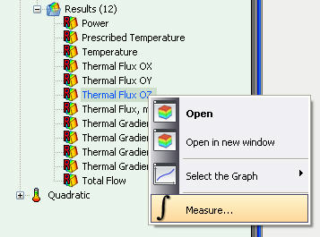
The command Measure is available now for results of thermal studies, such as Thermal flux and Power.
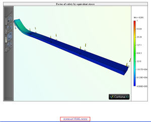
Report. A reference to loading the VRML viewer is added to the report.
New verification examples. Verifying examples are added for the new functionality: static calculations involving orthotropic materials and thermal contacts.


