Create Study
Step 1: Create the Frequency Analysis Study
Open the example model to start work.
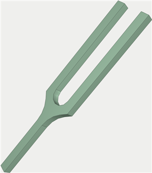
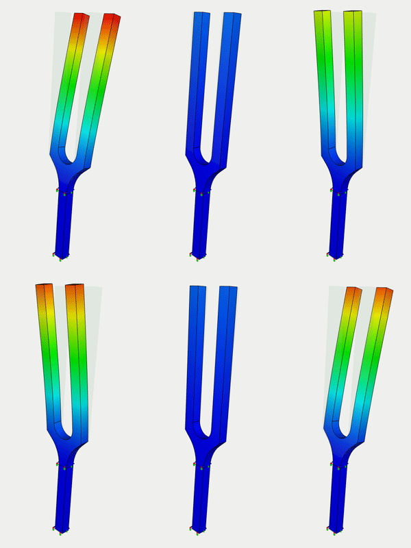
Let us calculate natural frequencies of the tuning fork shown on the picture.
Tuning fork - device for emitting a simple tone (pure tone) of the sound waves of a certain frequency. The frequency of the tuning fork sound depends on its size.
Tuning forks are used, for example, for tuning the musical instruments.
To create the Frequency Analysis problem, we need to carry out the following sequence of steps:
1.Invoke the New problem's properties window by one of the following methods:
|
Command Line: |
FEMASTUDY |
|
Main Menu: |
AutoFEM | Create a Study... |
|
Icon: |
|
2.Select the type of the study ( "Frequency Analysis" ) and add to the list ( "Selected Geometry" ) a solid:
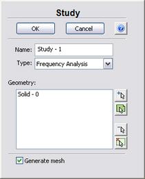
3.Since the option "Generate mesh" is activated, after setting up the problem, the system will automatically proceed to creating finite element mesh;
4.Press  for confirmation of New problem creation.
Create Mesh
Step 2: Create the Finite Element Mesh
After the problem setup, the system automatically proceeds to creating finite element mesh.
To create manually (or modify) the finite element mesh, we need to carry out the following sequence of steps:
1.Invoke the Mesh's properties window by one of the following methods:
|
Command Line: |
FEMAMESH |
|
Main Menu: |
AutoFEM|Create a Mesh... |
|
Icon: |
|
2.Let us build the finite-element mesh such that the edge length of an element will be no greater than 5.000 mm . The curvature is 32.
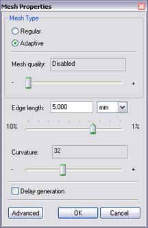
3.Press  for completing creation (or modification) of the mesh.
The result of mesh generation is displayed in the 3D window.
Now you will see the image of the mesh instead of the original part. The original part is not shown at this moment.
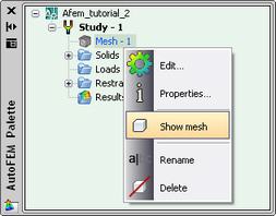
When it is necessary to hide or display again the finite element mesh, choose the element "Mesh" in the service window "AutoFEM Palette" , then invoke the command "Hide Mesh" or "Show Mesh" from the context menu (by pressing  ).
).
Create Constraints
Step 3: Define Restraints
To impose constraints on the displacements along the X,Y and Z axes of the coordinate system, we need to carry out the following sequence of steps:
1.Invoke the properties window of the Restraint by one of the following methods:
|
Command Line: |
FEMAFIX |
|
Main Menu: |
AutoFEM|Loads\Restrains|Fixture... |
|
Icon: |
|
2.In the properties window of the Restraint, it is necessary to select the entities to be constrained - faces;
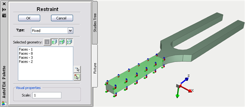
3.Press  to confirm Full Restraint creation.
Specify Material
Step 4: Specify Material
For each problem of the finite element analysis, it is important to correctly specify characteristics of the part's material.
To specify (or modify) the material, we need to carry out the following sequence of steps:
1.Invoke the material's properties window by choosing the solid in the service window "AutoFEM Palette" and performing the command "Material..." from the context menu (by pressing  ).
).
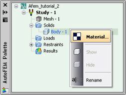
2.Provide a library of materials (into the group "Library");
3.From the list of materials, select, for example, "Steel AISI 1035";
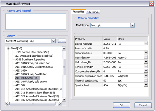
4.Confirm your selection by pressing  .
.
Working with AutoFEM Palette
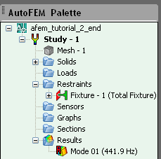
All problems of the document and their components are shown in the service window "AutoFEM Palette" in the form of the structured tree. This window appears automatically after creating the study. If it is necessary, it can be closed or displayed again with the help of the command:
|
Command Line: |
FEMAPAL |
|
Main Menu: |
AutoFEM | Studies Palette |
|
Icon: |
|
The element "Study" combines all components and objects specified for performing the calculation: finite element mesh ("Mesh"), constraints ("Restraints").
The folder "Results" is empty until calculation was successfully done.
Solve Study
Step 5: Solve the Study
After constructing the finite element mesh, specifying the constraints, the calculation can be performed.
To solve the problem, the following sequence of steps must be carried out:
1.Invoke the solution's properties window by one of the following methods:
|
Command Line: |
FEMASOLVE |
|
Main Menu: |
AutoFEM | Solve... |
|
Icon: |
|
2.Press  , to start calculation.

Customizing Results
After successful solution of the Frequency Analysis problem, we need to analyze the obtained results.
The list of results available for viewing is shown in the problems tree in the folder "Results".
To extend the list of results shown in the problems tree, the user has to:
1.From the context menu popping up upon pressing  on the name of the selected problem, invoke the window for customizing results (command "Results...");
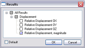
2.Check the results you need;
3.Press  .
.
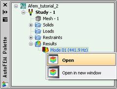
For viewing a result, select it with  in the problems window and select the command "Open". You can also use
 . The result will be shown in a new window of the Postprocessor.
Analyze Calculation Results
Step 6: Analyze Calculation Results
After successful solution of the Frequency Analysis problem, we need to analyze the obtained results.
The Frequency Analysis results include:
·natural frequency of vibration (Hz);
·natural mode shapes.
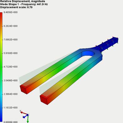
The natural vibration frequency corresponds to the expected resonance frequency of the structure. The natural mode shape, corresponding to a given frequency, shows what relative deformations the structure will undergo in case of occurrence of resonance. By analyzing the natural mode shapes, we can draw a conclusion about qualitative nature of the displacements but not about their actual magnitude.
The list of results available for viewing is shown in the problems tree in the folder "Results".
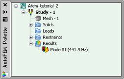
Open the result "Mode 01 (441.9 Hz)". Visually estimate the relative deformations (displacements) which the tuning fork will experience in case of occurrence of resonance at the natural frequency 441.9 Hz.
Report
Step 7: Generate a Report
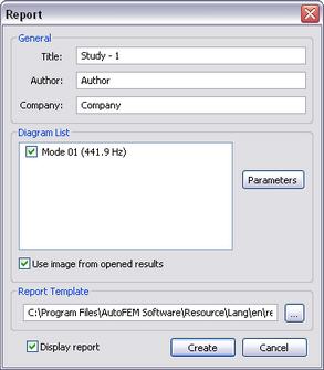
The user can create independent of the AutoFEM electronic documents which include the main information about the solved problem. The report is created in the html- format.
To create a report, the user needs to:
1.Invoke the dialog for customizing a report with the help of the command of the main menu: AutoFEM | Create Report...;
2.Fill in the fields in the group "General";
3.Tick the results, which have to be included in the report, in the "Diagram List";
4.Turn on the options "Use image from opened results" and "Display report";
5.Pressing the button  leads to appearance of the dialog for saving the report file.
Congratulations!
You successfully performed calculation of the natural frequencies of the structure with the help of the AutoFEM Frequency Analysis.
