
AutoFEM Training Course
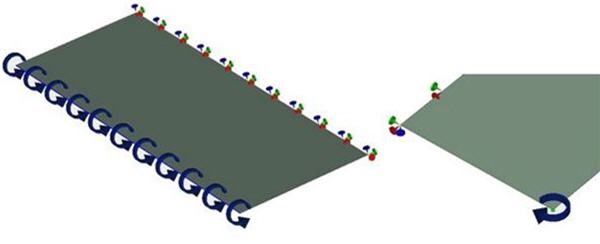
A joint - AutoFEM Software & NDAR - AutoFEM training course will be held in NDAR office (Antibes, France)
on 31 March-02 April 2015.
The course will be held in English, and other languages will be supported (French, Italian).
The course is for beginners and intermediate users of the program, and those interested in FE structural analysis. The materials covered include:
- Program environment and GUI, settings
- Types of studies
- Pre-processing: meshing , boundary conditions, materials
- User Coordinate systems
- ShipConstructor integration
- Processing, solver types
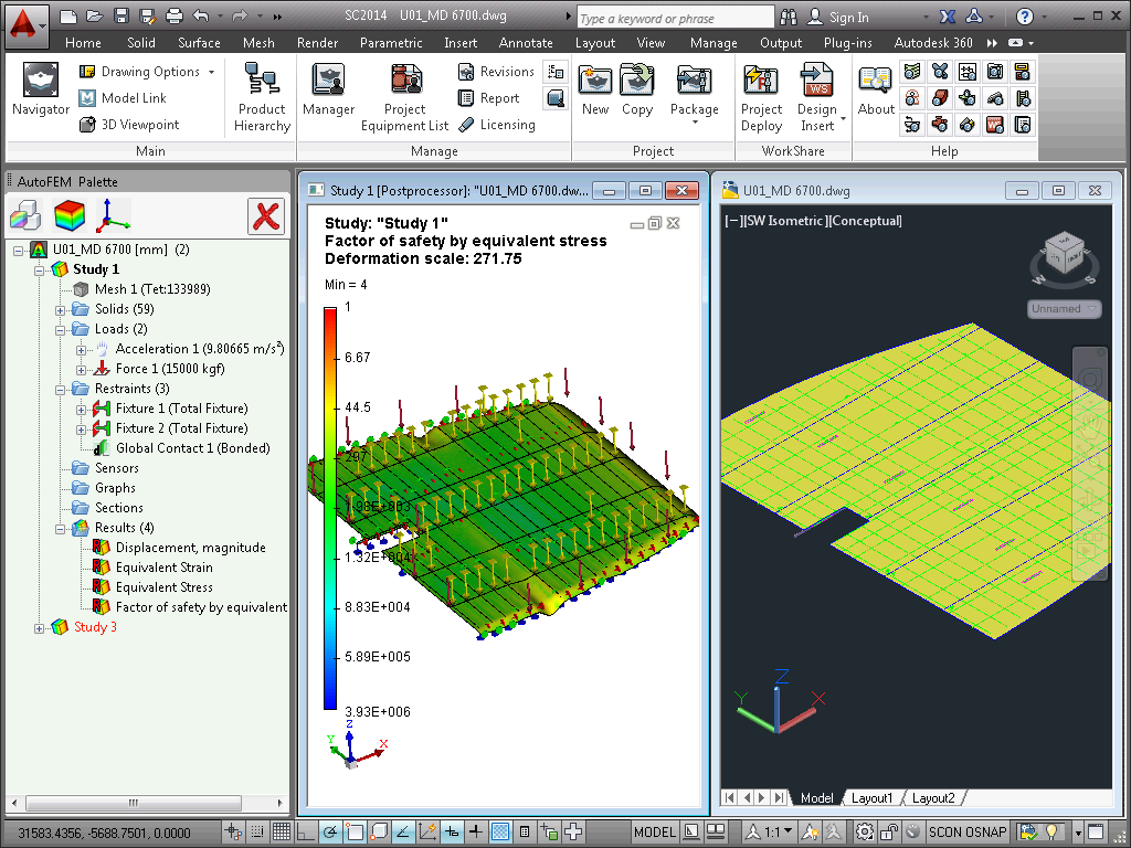
- Post processing: using sensors, graphs, colour diagrams, result sampling, reports
An AutoFEM license will be provided during the course free of charge. Participants should bring their laptops which should be running AutoCAD (Note AutoCAD 2011 is not supported). Although training models will be provided, participants are encouraged to bring their models, in order to work hands-on their own projects. Registration will be accepted on a first come first served basis, places are limited.
All course participants will be entitled to 20% discount in the purchase of software.
For more information or logistics questions, please contact Esta dirección de correo electrónico está siendo protegida contra los robots de spam. Necesita tener JavaScript habilitado para poder verlo..
Looking forward to seeing you at the course,
Contact persons:
Stéphane DARDEL. Nick DANESE
Design Systems & Technologies ™
150 rue de Goa, 06600 Antibes, France
tel +33-4-9291 1324 / fax +33-4-9291 1338
Esta dirección de correo electrónico está siendo protegida contra los robots de spam. Necesita tener JavaScript habilitado para poder verlo. / www.ndar.com

New features of AutoFEM Analysis 2.5
Support of AutoCAD 2015 and ShipConstructor 2015
Starting with the version 2.5, AutoFEM Analysis is compatible with eight different versions of AutoCAD, namely: AutoCAD 2007-2010 and 2012-2015 which work in the Windows XP/Vista/7/8 environment.
AutoFEM interface language selection
Starting with the version 2.5, the user can arbitrarily launch the software in one of five European languages: English, German, French, Italian or Spanish. On default, the system uses the language of AutoCAD in which it is being launched. If AutoFEM hasn’t a language interface (for example, Turkish), The English version is used. The user can select and set the AutoFEM interface language by pressing the button "AutoFEM Language Settings" and select the desired language. The selected language is assigned for all available AutoCAD versions and reflected in the corresponding column of the start dialogue. It is possible to simultaneously launch several instances of AutoCAD/AutoFEM with different language interfaces, running the AutoCAD/AutoFEM, then to change the language settings and run the next AutoCAD/AutoFEM instance.

Dialogue box of AutoFEM language settings

The selected language is shown in the AutoFEM start dialogue
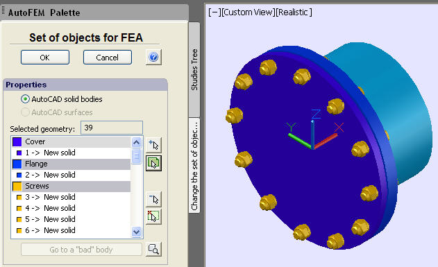
Improved dialogue box of the command “Set of Objects for FEA”
Measurement units of length. Now, the user can set the length units of the 3D model not only in the document settings but also directly in the process of creating a set of objects for FEA, extremely convenient. In the same dialogue, the user can change the units. On default, the units coincide with AutoCAD units of the current DWG file. The user is able to change these units not only while a set of objects is being created but at any time later in the same dialogue or in the Settings | Document page.

Measurement units can be defined while creating the set of objects for FEA
News of ShipConstructor Integration
Support of specific geometry such as Pipes. The options of ShipConstructor integration have been changed. A new opportunity to load from the ShipConstructor document a specific geometry (such as Pipes) has been added.

Option of the specific geometry import

ShipConstrutor pipes in the Preprocessor window

Solved study based on pipes
New iterative frequency / buckling solver
In AutoFEM 2.5, a new frequency and buckling solver is presented. Now the user can select between two methods of solving these problems - Direct (Lanczos algoritm) and Iterative.
Direct (Lanczos algorithm) uses a full inversion of the matrix to find the frequencies, therefore, it usually requires more random memory than the iterative method. It works fairly quickly to solve relatively small problems on powerful computer systems.
Iterative solver has lower memory requirements than the direct method because the inversion of the matrix is not needed. Therefore, it allows you to solve large frequency/buckling problems. The volume of studies is limited only by the calculation capabilities of the computer system, (first of all, available RAM and ROM).

New dialogue box of the frequency solver

New dialogue box of the buckling solver

Settings of a new frequency / buckling iterative solver
Searching for frequencies in the range
The possibility to seek resonance frequencies inside the defined frequency range by the user has been provided. The user should specify the lowest and highest frequencies and the number of them to be found. The system will seek resonance frequencies in the specified range.

The dialogue box of the interval frequency solver
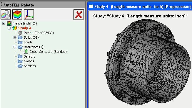
Common finite element mesh for several studies
AutoFEM allows the user to copy existing studies and use a copy as a base for a new finite element study. Since version 2.5, the user has the opportunity to control whether the original study and its copy have a common (single) finite element mesh, or if they are independent. On default, the system offers an independent finite element mesh for the copy of the original study.

Dialogue box for selection the mode of the command “Copy”
There are two available modes to copy the finite element mesh of the original study.
Create a new independent copy of the finite element mesh (default mode). It this case, each study (original and its copy) will have an independent finite element mesh. The user can recreate or edit the mesh in the copy of the original study to get different calculation results. This mode is often used to carry out several calculations with the different mesh size to confirm the convergence of the finite element solution to a stable value.
Use common finite element mesh for original study and its copy. In this case, the original study and its copy have a common (single) finite element mesh. Changing the parameters of the mesh influences both studies simultaneously and immediately. This mode is useful for combined calculations, for instance, when the results of the thermal study must be transferred to the static study and the finite element meshes must coincide. To destroy the link between meshes, delete the mesh in the desirable study and create it anew.
New service command «Physical properties”
This special command allows the user to get the values of the mass-volume properties of the selected objects (solids or surfaces). The command is available from the contextual menu on the selected object in the tree of studies or in the Preprocessor window. The command calculates volume / area / mass (if the material has been assigned) of the finite-element representation of the original objects and compares these original parameters with the same parameters calculated by AutoCAD functions for the original AutoCAD geometry. The difference between these values helps estimate the accuracy of finite-element representation of the simulated structure.

Retrieving the command "Physical properties"
Depending on the geometry selected for the finite element study, three types of the result table are available.

Table of volume-mass properties of the study based on 3D solids
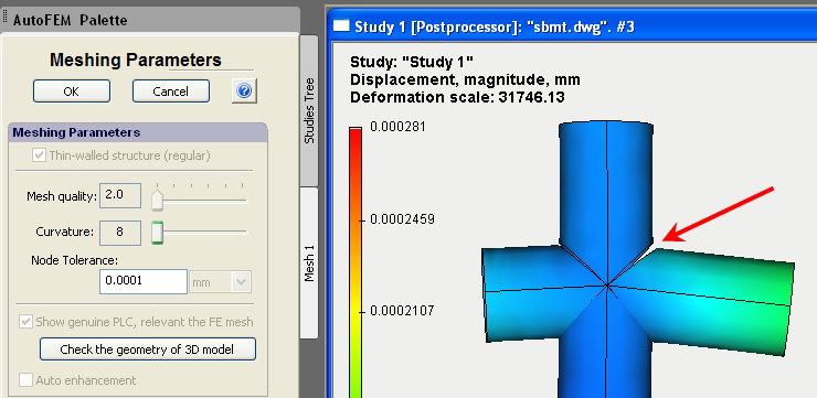
New additional option of 3d model diagnostics
Mode Find suspicious geometry. This mode allows the user to find very small entities of the 3D model such as extremely small steps, fillets or chamfers, which can prevent the successful creation of the tetrahedral finite element mesh (the mesh generator cannot divide them into tetrahedrons). If the mesh is not created, you should modify these elements of geometry to eliminate errors. The aspect ratio defines the threshold value when the object may be considered as an erroneous object.

Very small step
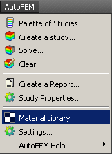
New access to the AutoFEM material library
Access to the AutoFEM material library has been facilitated. Now the user can open library of materials by three ways: using main AutoFEM menu, AutoFEM Ribbon or the button of a quick access on the top of the AutoFEM Palette.
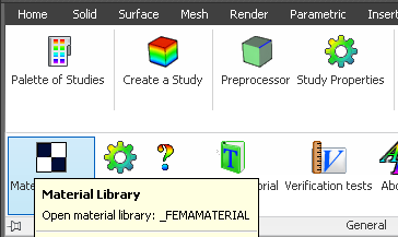
New ways of the access to the AutoFEM material library
AutoFEM Help in the Spanish language
Full text and context dependent help is now available in the Spanish language.

AutoFEM Help in the Spanish language
New lesson on AutoFEM & ShipConstructor Integration
A special interactive lesson on the theme of AutoFEM & ShipConstructor Integration has been added in AutoFEM Tutorials

New lesson about joint work with ShipConstrutor
Many other small and medium improvements have been realised.
Important! Please read before the upgrade of the commercial version.
To transfer licence 2.x to 2.5, you must deactivate the licence 2.2 before uninstalling the software. Then, uninstall the previous AutoFEM version, install AutoFEM 2.5 and activate the software anew using the same serial number. To deactivate the licence, use a special command in the AutoFEM folder.

Menu item "Deactivate Licence"
AutoFEM Analysis 2.0 build 5670 (09 October 2013)
The problem of opening files DWG from Windows Explore or from lessons of AutoFEM Analysis Tutorial, while AutoCAD is not working, is eliminated.
In the assembly of AutoFEM Analysis 2.0 build 5669 dated 17 Sep 2013, files DWG could be opened with error because of the slowed loading of AutoFEM modules. This problem manifests itself in the assembly 5669, only if AutoCAD has not already been launched while you are doing a double-click in Windows Explore in the file DWG with saved data of AutoFEM Analysis.
In assembly 5670, if you open a file via the Windows Explore under condition of not launched AutoCAD, you also can see the following message (it may not appear):
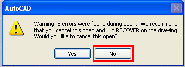
It is necessary to continue the procedure of opening the document (press "No"). After AutoCAD will be fully launched, all data of AutoFEM will be accessible for work. All users of AutoFEM Analysis 2.0 build 5669 are strongly recommended that the version should be immediately updated; as the file format was changed (earlier created studies are to be re-created).
New features of AutoFEM Analysis 2.2
Integration with ShipConstructor
Based on AutoCAD, ShipConstructor is the leading software product for ship design and ship building, adopted worldwide. ShipConstructor provides the tools needed to design, model and prepare production documentation for any type of vessel, be it a ship, a submarine or an offshore platform.
In the course of designing a vessel or an offshore structure, it is necessary to verify its strength and stiffness characteristics, preferably using Finite Element Analysis. Thanks to direct integration of AutoFEM Analysis and AutoCAD, ShipConstructor users can now use AutoFEM to transparently run FEA analysis of ShipConstructor models.
As of AutoFEM Analysis v2.2, the integration with ShipConstructor is complete. The ShipConstructor 2014 stock catalogue supports the mechanical properties of materials needed for FEA, and AutoFEM reads the full model topology directly, including:
• Names of parts
• Names of AutoCAD layers (for parts in the current document)
• Data about the material (name, grade, etc.). If the user has not specified thee, they will be taken from the native AutoFEM Analysis materials library, using a name matching technique.

Settings of integration with ShipConstructor
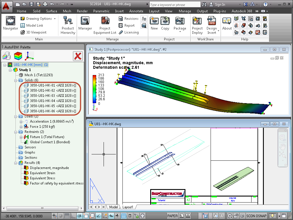
ShipConstructor parts and all related information are acquired by AutoFEM Analysis, and
if needed, ShipConstructor materials are name-matched with materials in the AutoFEM library.
Calculation example of a ShipConstructor Assembly
More information about joint work of AutoFEM & Shipconstructor can be found here:
AutoFEM Analysis & ShipConstructor Software: Working Together
or here
AutoFEM Analysis & ShipConstructor Software: Working Together (pdf)
Work with the AutoCAD blocks
The new version of AutoFEM Analysis allows the user to work more effectively with AutoCAD blocks. In the process of creating a set of objects for the finite-element analysis, the system analyzes the content of the block and processes each object contained in the block as the individual solid body. Then, each element of the block may have its own material, and one may even carry out an individual analysis for each solid contained in the unit. It is also possible to activate the single-body mode for the unit. In this case, the collection of parts will be considered as one, and the selected material used for all the components (parts).

Processing the group of parts as a unified solid-body object

Calculation example: the block is considered to be one solid body

The block is analyzed as the aggregate of the several bodies composing it,
which were created in AutoCAD
New utility of setting up "FEMA Tool"
Launch of AutoFEM Analysis from the Start menu. The AutoFEM Analysis utility "FEMA Tool" has been completely redeveloped, and AutoFEM Analysis can now be launched directly from the All Programs|Windows menu. In the dialogue, the user chooses the AutoCAD version using which he or she wishes to launch AutoFEM Analysis.

Shortcut for launching AutoFEM Analysis from the All Programs Windows menu

Dialogue hosting the configuration and launching of AutoFEM Analysis
In the "FEMA Tool" utility dialogue, one selects the version of AutoCAD in which to run AutoFEM Analysis, and identifies the licence server by its network address.
Materials: new possibilities
Material parameters shown in user defined units (other than SI)
The materials library now documents the physical properties of materials, in the user-selected system of units. The user-selected unit system is stored by the system and remains available thereafter.
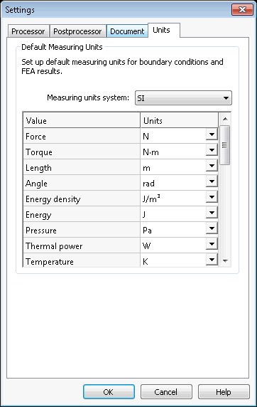
Choosing the unit system
Copying materials
Materials can be copied within the user library. The copies can then be edited to obtain new materials with new physical properties.

Copy of materials and user defined units are available
New ways to work with AutoCAD layers
Using AutoCAD layers for grouping objects within the Study
Objects included in the Study are grouped by layer and identified in the list by the name and colour of the layer.
Objects in the Study are grouped by layer
Assigning the material by layer
It is now possible to assign a material in one step to all solids placed in the same layer.
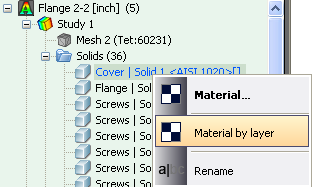
New command "Material by layer"
Assigning the thickness of plate parts by layer
It is now possible to assign a thickness to all structural shell parts located on the same layer.

New command "Thickness by layer"
New methods of creating coordinates systems
The command used to create a user coordinate system has been greatly improved.Along with the ability to import coordinate systems from AutoCAD, it is now possible to create and orient the coordinate systems, selecting vertexes of the 3D model in the Preprocessor window.
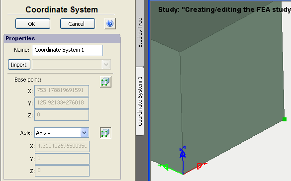
Use of the 3D model vertexes to define the UCS
New options to generate a tetrahedral mesh
Two new options have been added to the command used to generate tetrahedral meshes:
Do not create elements which are too small. This option allows restricting the generation of small finite elements in order to decrease the total number of elements and cut the number of the problem dimensions without prejudice to the calculation accuracy. This option is activated by default.
Remove erroneous tetrahedrons.This option automatically removes poor quality tetrahedrons during mesh creation,thereby avoiding the need for geometrical corrections during calculation runs. This permits a more reliable transfer of calculation results from one study to another (for instance, to transfer the results of thermal analysis to static analysis for calculation of thermal elasticity). This mode is activated by default.
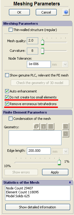
New options of mesh generator
New selection tool to identify objects located in one plane
A new selection tool analyses boundary conditions and finds all the objects lying in one plane. First, one selects the entities of 3D model (facets or two edges located in one plane, or three vertices). Then, using the new selection button, all the coplanar objects from that selection (facet, edge, or vertex) are selected and grouped. This possibility essentially facilitates the preparation of the finite-element model of large assembly structures, consisting of hundreds or thousands of parts.
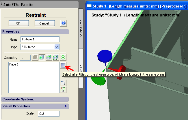
Select the first facet

All facets lying in the same plane as the first selected facet
are automatically added to the list when pressing the button
New boundary condition – Plane of Symmetry
This command allows to define the planes of symmetry of a structure, i.e. the planes relative to which the structure’s deformation is supposed to be symmetrical. As a rule, the planes of symmetry are used to cut the dimensionality of a problem being solved, at the expense of the possibility of analysing only one part of the structure. At that, the multiple (at least by 2 times) decrease in the number of algebraic equations (at the same level of discretization) is achieved.

Dialogue of the Plane of Symmetry command

Calculation example: use of symmetry to decrease the problem
New report generation dialogue
Working with the report generation dialog has been made much easier. Management of the output results has been streamlined, and the creation of the 3D VRML model, used to display results, has been improved. By default, the VRML model will not be created if the number of finite elements exceeds 50,000. The user is able to set the threshold value.

New dialog of Report settings
Creation of VRML models of results has been improved
Generating VRML models of results is now optimized as function of visibility.

Non-linearity in static problems for models based on AutoCAD Surfaces
Support of geometric non-linearity now possible for static analysis using shell finite elements.
")
Geometric non-linearity is supported using plate finite elements (shells)
Calculation info
A Study Properties page documenting the result of the latest successful calculation has been added, a very useful reference.
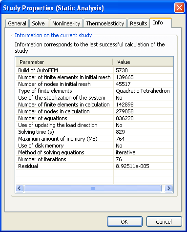
New tab Info contains main information about the solved study
Attention!
If while opening the DWG file, containing the saved studies of previous AutoFEM version, you see the AutoCAD error messages, remove the previous data of AutoFEM Analysis with the help of the command _FEMAERASEALL  and recreate the studies.
{source}
<script src="https://apis.google.com/js/platform.js"></script>
<div class="g-ytsubscribe" data-channelid="UCE62j8F63nM3QX5gsQj0Grg" data-layout="full" data-count="hidden"></div>
{/source}
New features of AutoFEM Analysis 2.0
Support of AutoCAD 2014 and Windows 8
Now AutoFEM Analysis 2.0 is compatible with seven versions of AutoCAD, namely: AutoCAD 2007-2010 and 2012-2014 which work in the Windows XP/Vista/7/8 environment.

AutoFEM Analysis 2.0 works with AutoCAD 2014
Work with surface (shell) 3D models
New AutoFEM version maintains the full-fledged working with finite-element models based on triangular elements of plates. This allows for more effective analysis of strained state of different thin-wall structures, which are common in the routine practice of the contemporary machine-building and construction sectors. Such structures include reservoirs, construction structures, shipbuilding structures, aviation products and so on.

Analysis of shell structures is available in AutoFEM Analysis 2.0
Two types of plates’ finite elements are supported: with linear and quadratic approximation.
A study with the use of shell elements can be created both on the basis of a surface model of AutoCAD and by facets of the 3D solid-body model.
Shell finite-element models are available for solving the following problems:
- Static Analysis
- Frequency Analysis
- Buckling Analysis
- Fatigue Analysis
- Forced Harmonic Oscillations
- Thermal Analysis
New possibilities of the Preprocessor
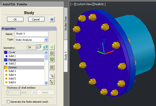
New command. Set of objects for FEA.
The approach to creating finite-element studies was changed radically. The notion “Set of objects for FEA” was introduced in the new version. This set includes AutoCAD objects (3D solids or surfaces), for which studies will be further created. Only one set of objects exists in a document. All studies, regardless of their number in the document, are created on the basis of the same object set. At the same time, the set of objects, included in each specific study, is independent of other studies, so it may vary.
New command "Set of objects for FEA"
The presence of the set of objects gives the following advantages and provides for the work convenience:
• The improved possibility of editing studies. In particular, bodies from the set can be added (or removed) to the study without losing already applied boundary conditions.
• It is much more convenient to manage the composition of the study, adding and removing the bodies from the interface of the window of the AutoFEM Analysis Preprocessor.
In case of changing the initial objects of the model in AutoCAD, included in the set, diagnostic message appears, but the body set and problems remain unchanged until the user updates them.
Working with layers
When creating the body set, the system uses AutoCAD layers for logical partition of objects in the set of objects intended for the finite-element analysis. The list of objects contains the colour marker of the layer, with the colour and name of the latter; besides, all objects on the list are grouped by layer. Objects which are contained by invisible (switched-off) layers do not fall in the body set. Grouping objects by layer is convenient when working with assembly models, made of tens and hundreds of objects.

Additional indication of failed objects by colour
If, at obtaining the geometry from AutoCAD, an unavoidable error has appeared, the erroneous object on the list is marked by colour.
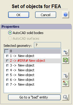
Indication of erroneous object by colour
Indication of units of measurement of the 3D model
The tree of study and the Preprocessor window now display the current dimensionality of the 3D model’s spatial units, for instance, in inches or millimeters. It allows the user to escape possible errors in interpretation of computational results.
Indication of length measure units of the 3D model
Erasing AutoFEM data
The new command for erasing all AutoFEM data from the AutoCAD file. The command allows for permanent erasing of all data of AutoFEM Analysis from the AutoCAD file dwg (including the data of previous versions of AutoFEM Analysis).
|
Command Line: |
FEMAERASEALL |
|
Icon: |
|
Editor of materials
The process of creating SN-curves was changed. The data of the curve are imported in the Windows exchange buffer, where the data must be presented in the form of two columns with the separation by space between values and the line feed between rows. The table can be typed in the Windows NotePad or, by way of illustration, in Excel.

New command Nodal torque
To set up boundary conditions on ribs and vertices of the surface models (shells), the new command, “Torque at nodes”, was introduced.
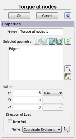
Indication of Nodal torque in the Preprocessor window
Mesh generator
The overall stability of the work of the tetrahedron mesh generator was increased. New tools of diagnostics for correctness of the 3D model were added.
If, in the process of constructing the tetrahedron mesh, the algorithm encounters the insuperable obstacle, the diagnostic message is given, and the system points at the area of geometry or shows the number of the “bad” body at the model. The user can try and eliminate the problem in the 3D model geometry or exclude the "bad" body from the finite-element study.

Indication of the place where there is an error of 3D model geometry
Node tolerance
The possibility of managing the accuracy of nodes’ coupling was added. It can be useful from the points of obtaining mesh models by surfaces, butt-jointed by segments, and of eliminating possible ruptures at the borders of segments.
Rupture of the mesh model

Removing the gaps by increasing the node tolerance
Opening the file with results has been optimized.
Working with big data array. The working of the Postprocessor window (speed of opening the window with results) with big results (many millions of degrees of freedom) was optimized significantly.

Example of study consisting of 225 solids and having ~17 million degrees of freedom
By default, the obtained result "Displacement" is imaged in the units of measurement of the initial 3D model.
New possibilities of the Processor
Additional acceleration of direct and iteration static solvers. Due to optimizing the algorithms, we achieved a pronounced increase in the speed of solvers’ working to solve systems of finite-element equations.

Window of static solver in the process of finding solution of the system of 29 million equations
The working with big results was significantly improved concerning the computation of parametric problems (non-linear static, unsteady thermal process, forced oscillations) at big number of steps that permits to create data array exceeding the size of the operational memory (dozens of GBs) and have a possibility of their efficient analysis even by computers with the small size of the operational memory.
News of AutoFEM Analysis Lite
The updated ribbon of commands. Inaccessible commands are imaged by grey icons, while available commands, by coloured icons.


New icons of AutoFEM Analysis Lite 2.0
Thermal power. In AutoFEM Lite 2.0, it is permitted to use the command “Thermal power” for thermal analysis problems.
Improved compatibility with commercial version of AutoFEM. AutoFEM Lite 2.0 permits to open results of the computations obtained in the AutoFEM Analysis 2.0 commercial version. Now, AutoFEM Lite can be used as a free-of-charge viewer of the results of the computations obtained in the AutoFEM Analysis commercial version. The user can also view initial data for the study (loading and materials’ parameters) and generate an html-report.

AutoFEM Lite 2.0 opens the results of AutoFEM Analysis 2.0
Network licence
AutoFEM Analysis 2.0 can be delivered with the local and network check of a licence. The network licence is convenient for administration at the work of a great number of users as it allows for the work organization in the mode of the “floating” licence when access to the system is possible from any computer in the network, with the number of such computers equaling the amount of the paid licences.
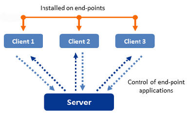
Layout of work of the network licence
Accompanying materials and learning aids
Installation guide
The system’s distribution package includes an installation manual in five languages.

Multilingual Help
AutoFEM Analysis 2.0 has a comprehensive context-dependent help in three languages: English, German, and French.
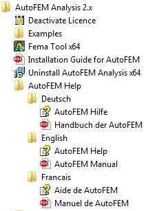
Lessons in five languages
Now, interactive lessons in AutoFEM Analysis 2.0 are available in five languages. Lessons include step-by-step instructions for each type of study; the teaching film with text comments and saved example files with the results of computations.

Tutorial of AutoFEM 2.0 is available in the five European languages

Start window of AutoFEM Analysis Tutorial (English)
Verification examples
The number of verification examples, characterizing the accuracy of the computations, now is about 90. The examples’ descriptions are available in five European languages.

Verification examples are included in the separate distribution package and are available to be downloaded from the website by the following link: https://autofem.com/downloads/files/autofem_verifications.zip
Notes concerning the transfer to version 2.0 from version 1.7
AutoFEM Analysis 2.0 can be installed on the computer and exist together with the previous version (AutoFEM 1.7). However, AutoCAD can work in a snap only with one of these versions (2.0 or 1.7), i.e. two AutoFEM versions cannot be reflected in AutoCAD simultaneously, but they can be used in turn. Management of the version being loaded is performed by utility Fema Tool.
In the end of installation of AutoFEM 2.0 on the computer with the installed version AutoFEM 1.7, the following dialogue will appear which will show the AutoCAD versions installed in the system.
To articulate the version 2.0 rather than 1.7 in AutoCAD, you need, in the dialogue of the Fema Tool utility of the AutoFEM version 2.0, to remove a tick opposite to the required version of AutoCAD, press Apply, set the tick again, and press Apply.
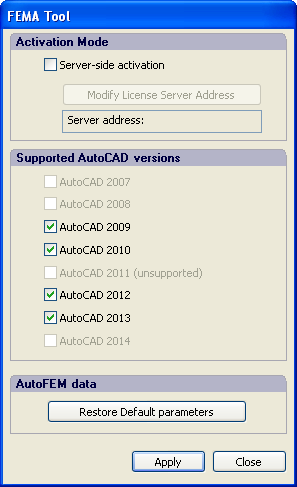
Fema Tool window of AutoFEM 2.0
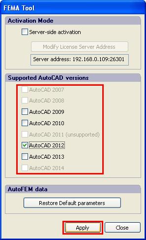
Remove ticks to unregister AutoFEM 1.7 in AutoCAD 2009, 2010, 2013 and press Apply.
AutoFEM 1.7 remains registered in AutoCAD 2012.
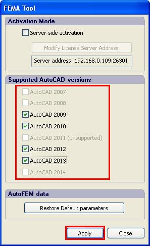
Put ticks opposite to AutoCAD versions where we want to register AutoFEM 2.0 and press Apply.
In the figure, AutoFEM 2.0 is registered in AutoCAD 2013,
and AutoFEM 1.7 remained registered in AutoCAD 2012.
Similar actions to unregister AutoFEM Analysis in AutoCAD shall be executed when the system is to be removed or when the language interface of Windows is modified.
Attention!
AutoFEM Analysis 2.0 does not open the saved studies of version 1.7!
You must create the relevant studies anew. Also, it is mandatory to remove the previous data of AutoFEM Analysis 1.7 with the help of the command FEMAERASEALL .