
Neue Funktionen von AutoFEM Analysis 2.8
Unterstützung von AutoCAD 2016 und ShipConstructor 2016
Beginnend mit Version 2.8, ist AutoFEM Analysis kompatibel mit neun Versionen von AutoCAD, nämlich AutoCAD 2007-2010 und 2012-2016, welche auf der Plattform Windows XP/Vista/7/8/10 laufen.

Überarbeiteter Installer von AutoFEM Analysis
Beim Installer von AutoFEM Analysis wurde die Installation von Pflichtprogrammkomponenten (Microsoft Visual Studio redistributable packages) hinzugefügt, welche für die Systemfunktion benötigt werden. Der Installer erkennt installierte AutoCAD-Versionen und ermöglicht es dem Nutzer Pakete zu installieren, welche für die Arbeit mit der jeweiligen AutoCAD-Version benötigt werden.

Dialog zur Installation von Pflichtprogrammkomponenten von Microsoft
Programmstartdialog
Der Launcher wurde überarbeitet und verbessert. Insbesondere wird AutoFEM jetzt standardmäßig im Modus "autoload" gestartet (d.h. AutoFEM wird in AutoCAD gleichzeitig beim Start von AutoCAD hochgeladen).

Außerdem sind alle Aktionen bei der Konfigurierung der Lizenz und Lizenzbearbeitung, wie zum Beispiel "Aktivierung/Deaktivierung" von Lizenzen, im Startdialog durch Drücken des Buttons "Configure licence" verfügbar (früher wurde der Zugang zu diesen vom Windows-Menü bewerkstelligt).
 and of activation/deactivation of the licence")
Dialog zur Verwaltung vom Lizenztyp (Netz oder lokal) und der Aktivierung/Deaktivierung von Lizenzen
Neue Funktionen vom Preprozessor
Verwendung der Progress Bars bei der Ausführung von Datenverarbeitungsoperationen
Die meisten bei großen Modellen länger durchzuführenden Operationen (wie zum Beispiel der Erhalt eines Modells von AutoCAD im Laufe der Erstellung von einer Sammlung an Körpern für FEA) verwenden jetzt Progress Bars, welche die aktuelle Arbeitsetappe anschaulich anzeigen und es ermöglichen, das restliche Arbeitsvolumen bis zur Erfüllung der Operation einzuschätzen. Die Progress Bar zeigt die Anzahl bereits bearbeiteter Objekte und die Gesamtzahl der Objekte an, was es ermöglicht indirekt ebenso die Zeit einzuschätzen, welche zur Erfüllung der aktuellen Etappe benötigt wird.

Die Progress Bars zeigen anschaulich den Prozesszustand vom Erhalt des 3D-Modells von AutoCAD an.
Verbesserter Dialog des Befehls "Set of Objects for FEA"
Es wurde die Möglichkeit zur Bearbeitung der Glätte von Abbildungen runder Oberflächen im Fenster des Preprozessors beim ersten Erhalt der Geometrie des 3D-Modells von AutoCAD hinzugefügt. Ein spezieller Slider ermöglicht es dem Nutzer die minimale Genauigkeit der Approximation von gekrümmten Elementen des 3D-Modells zu bestimmen.

Ein Zylinder mit kleinem Durchmesser wird durch ein Oktogon approximiert

Eine genauere Approximation desselben Zylinders durch ein Polygon mit 24 Segmenten
Neue Möglichkeiten des Befehls Aufgabendiagnostik
Ausschließung von hängenden (dangling) Körpern aus der Verrechnung
Beim Befehl "Aufgabendiagnostik" gibt es jetzt die Möglichkeit "baumelnde" (dangle) Körper und Körpergruppen aus der Verrechnung ohne deren Löschung aus dem Aufgabenbestand auszuschließen. Als "baumelnde" Details werden einzelne Details oder kleine Detailgruppen genannt, welche nicht mit anderen Details vom 3D-Aufbau kontaktieren, d.h. sie "schweben" sozusagen im Raum. Solche Objekte können für gewöhnlich nicht unmittelbar an mechanischen Festigkeitsberechnungen teilnehmen, wenn diesen keine Befestigung im Raum zugeteilt wird, d.h. sie werden bei Kraftaufwand in die "Unendlichkeit" verschwinden. Diese Option macht es möglich die Festigkeitsberechnung sogar dann durchzuführen, wenn im 3D-Modell eine Vielzahl an getrennt angeordneten unbefestigten Objekten (und diese können unberücksichtigt sein) vorhanden ist.

Die baumelnden Körper werden im Fenster des Preprozessors in grün hervorgehoben
Neue Möglichkeiten des Netzgenerators
Korrekte Arbeit mit Multi Volume Objects
Die neue Version des Netzgenerators ermöglicht die Verwendung so genannter mehrvolumiger Körper (d.h. Körper, die aus mehreren nicht miteinander kontaktierenden Volumen bestehen) bei Untersuchungen. Dies vereinfacht erheblich die Vorbereitung des Entwurfsmodells bei einem Vorhandensein von multivolumigen Körpern. Bei den Vorgängerversionen von AutoFEM war das Vorhandensein von multivolumigen Körpern ein unüberwindbares Hindernis auf dem Weg zur Erstellung eines FEM-Netzes.

Die Diagnostik des 3D-Modells diagnostiziert nach wie vor multivolumige Körper

Das Vorhandensein von multivolumigen Körpern ist beim Aufbau des FEM-Netzes kein Hindernis mehr
Verbesserungen bei der Arbeit mit dem ShipConstructor
Effektive Arbeit mit großen Modellen im ShipConstructor
Dank der Verbesserung einiger Funktionen von AutoCAD, beginnend mit der Version AutoCAD 2015 und insbesondere AutoCAD 2016, ist AutoFEM Analysis nun in der Lage große 3D-Aufbaumodelle vom ShipConstructor zu verarbeiten, welche für gewöhnlich über tausende von dreidimensionalen Detailmodellen verfügen.

AutoFEM ist in der Lage Aufbauten zu verarbeiten, welche aus tausenden Objekten bestehen, einschließlich Schiffsrumpfteilen
Verbesserung des Moduls zur Integrierung mit ShipConstructor
Verbesserte Option für den Erhalt spezifischer Geometrie vom ShipConstructor. Mit spezifischer Geometrie bezeichnen wir Details, welche für die FEA-Analyse nicht durch standardmäßige Mittel von AutoFEM ausgewählt werden können, da sie über einen spezifischen Typ verfügen, der nicht mit dem Typ 3D-Solid in AutoCAD übereinstimmt. Die Option ermöglicht es unter anderem die gekrümmte Geometrie vom Unterwasserrumpf von Schiffen, Rohrelementen zu erhalten, sowie die Liste der erhaltenen Körper zu führen.

Verbesserter Dialog der Integration mit ShipContructor
Arbeit mit Schiffsrumpfteilen
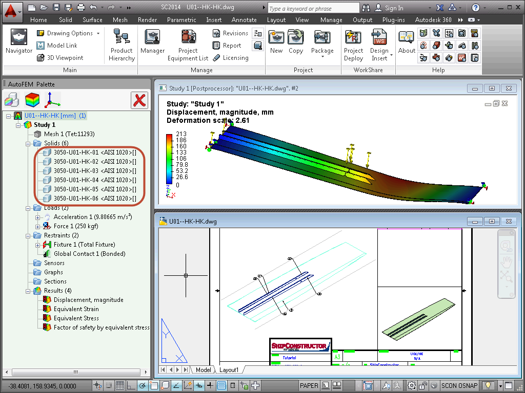
Eine Reihe spezieller Instrumente für die Arbeit mit Rumpfteilen von Schiffen wurde speziell entworfen, um den Bedürfnissen von Schiffsbauingenieuren, den Nutzern vom ShipConstructor nachzukommen. Als wesentliche Methode für die Festigkeitsanalyse von einstückigen Schiffskonstruktionen (Units) empfehlen wir es laminare FEM-Darstellungen von Entwurfsmodellen zu verwenden, welche auf der Grundlage von dreidimensionalen Hartkörpermodellen der Konstruktion erstellt werden.
Version 2.8 bietet eine spezielle Auswahl an Instrumenten für die Bewerkstelligung der Möglichkeit zur Erstellung von Aufgaben mit Schiffsrümpfen, unter Berücksichtigung der spezifischen Darstellung dieser Konstruktionen, die im ShipConstructor verwendet wird.
Erstellung von Aufgaben mit rumpfförmigen Objekten
Für diese Zwecke wird eine Objektklasse (SCONCURVEDPLATE) verwendet, welche die krummlinige Geometrie in Form einer Gesamtheit von dreieckigen oder viereckigen Rändern mit Dicke darstellt. Im Prozess des Erhalts vom 3D-Modell von AutoCAD, fasst AutoFEM Analysis 2.8 die Gesamtheit dieser Ränder korrekt zu einem Rand zusammen, was die Eingabe von grenzenden Bedingungen ermöglicht, die diesen Konstruktionselementen auferlegt werden.

Rumpfteil des Schiffs im Fenster von AutoCAD/ShipConstructor

Rumpfteil des Schiffs im Fenster vom Preprozessor AutoFEM Analysis
Anwendung der verteilten Belastungen auf die Schiffskörper
Bei der Erstellung von Aufgaben in der laminaren FEM-Aufstellung gruppiert das System automatisch Facetten, welche die Geometrie des Schiffskörpers beschreiben, in einen zusammengefassten Rand, was es ermöglicht diese Konstruktionselemente in einem Klick für die Anwendung von verteilten Grenzbedingungen auszuwählen (Druck, Kraft usw.).

Anwendung der Belastung "Wasserdruck" auf die Schiffskörperelemente
Eingabe von Grenzbedingungen für die Rippenketten
Bei der Arbeit mit FEM-Modellen auf der Grundlage von Platten werden die Grenzbedingungen auf die Ränder und Rippen auferlegt. Spezielle Instrumente ermöglichen es, die Anwendung von Grenzbedingungen auf die Rippen zu vereinfachen, indem sie eine Vielzahl an Segmenten einer Rippe ermöglichen, wodurch einfach das erste und letzte (folgende) Segment angegeben wird. Das System fügt automatisch alle Zwischensegmente zur Auswahl hinzu, welche zwischen den Ausgewählten liegen und zu einem Körper gehören. Diese Funktion ermöglicht es die Grenzbedingungen auf Rumpfränder anzuwenden, die aus dutzenden und hunderten von Segmenten bestehen.

Auswahl einer Segmentkette der Rippe für die Eingabe der Grenzbedingung
Eingabe von Grenzbedingungen für krummlinige Körperoberflächen
Bei Belastungen, die auf Ränder angewendet werden (Kraft, Druck, Moment, Traglast, zusätzliche Masse), gibt es jetzt die Möglichkeit in einem Klick die komplette Detailoberfläche auszuwählen, auch wenn diese in viele Facetten aufgeteilt ist, was kennzeichnend für Details vom Rumpftyp ist, die im ShipConstructor erstellt werden. In einem speziellen Dialog gibt der Nutzer die zulässige Abweichung der Norm (in Grad) ein, wodurch das System mit der Orientierung auf diese Norm Facetten auswählt, deren Normen nicht mehr als um den Wert der Nachbarfacetten abweichen, und Grenzbedingungen auf die Gesamtheit der Facetten in einem Klick anwenden wird.

Automatisierte Auswahl des krummlinigen Rands vom Detail, welches durch viele Facetten approximiert wird
Neuer Ansatz zur Modellierung von dünnwandigen Konstruktionen
Automatische Konvertierung einer volumigen FEM-Aufgabe in eine laminare
Die meisten typischen Konstruktionen beim Schiffsbau (Schiffe und Uferwerke) werden zu 90-95% aus Stahlplatten und Profilen hergestellt. Es ist allgemein bekannt, dass die FEM-Analyse solcher Konstruktionen mit volumigen finiten Elementen (solchen wie Tetraedern oder Sechskanten) aus rechnerischer Sicht oft schwer ausführbar sein kann (d.h. zu viel Systemmittel erfordern kann). In der Theorie und Praxis von FEM-Berechnungen ist es üblich zur Bewertung des belasteten Zustands solcher Konstruktionen finite Plattenelemente (Schichten) mit dreieckiger oder viereckiger Form zu verwenden.
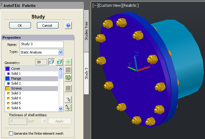
Beginnend mit Version 2.8 wird im Dialog der Aufgabenerstellung anschaulich eine Auswahl abgebildet, in welcher FEM-Aufstellung (volumig oder laminar) der Nutzer die FEM-Untersuchung erstellen möchte. Für die Modellierung einstückiger Schiffskonstruktionen, welche im Wesentlichen aus Metallplattendetails bestehen, empfehlen wir es eine FEM-Modellierung mit Plattenelementen zu verwenden.

Auswahl der Option zur Erstellung einer Plattenaufgabe auf der Grundlage eines dreidimensionalen Hartkörpermodells
In AutoFEM Analysis 2.8 wurde ein intellektueller Algorithmus realisiert, welcher es ermöglicht, das Entwurfsmodell automatisch zu erstellen, das dreieckige finite Plattenelemente für die Konstruktion aus 3D-Soliden verwendet.
Die Arbeitslogik vom Algorithmus berücksichtigt, dass alle Konstruktionselemente als Plattendetails vorgesehen werden können. Das System analysiert die Detailgeometrie und wählt automatisch die Oberfläche mit der größten Fläche von jedem Detail für die Teilnahme an der Berechnung aus. Bei der Auswahl vom Rand des 3D-Solids wird die Zuordnung des Details im Verhältnis zu anderen kontaktierenden Details berücksichtigt. In der Regel wird für die Teilnahme an der Berechnung der Rand gewählt, welcher über die meisten Kontakte zu Nachbardetails verfügt. Das System bestimmt automatisch die Dicke des Plattendetails. Der Nutzer kann sowohl die automatische Systemauswahl (d.h. die Auswahl oder Hinzufügung eines anderen Rands zur Berechnung), als auch die Dicke, welche vom System für das bestimmte Detail zugewiesen wurde, ändern. Dies ermöglicht es dem Rechner das laminare FEM-Modell flexibel zu korrigieren, indem die größtmögliche Übereinstimmung des Entwurfsmodells mit dem originalen Festkörperprototyp erreicht wird. Im Laufe der automatischen Erstellung des äquivalenten Plattenmodells analysiert das System die Zuordnung der Konstruktionsdetails und versucht die Beständigkeit der Konstruktionstopologie im Ganzen zu bewerkstelligen, was bedeutet, dass die Details, welche im ursprünglichen 3D-Festkörpermodell kontaktieren, nach Möglichkeit auch in deren Plattenapproximation kontaktierend bleiben. Der Nutzer kann diesen Prozess steuern, indem er die Option "Restore topology of the structure" im Dialog der Aufgabenerstellung ein- oder ausschaltet. In demselben Dialog werden die Optionen für die automatische Zusammenfassung von Facetten in einen gemeinsamen Rand und eine Grenzschwelle für die zulässige Anzahl von Facetten für die automatische Geometrieauswahl, die bei der Untersuchung miteinbezogen wird, eingegeben.

Optionen des Befehls zur Erstellung einer laminaren FEM-Aufgabe, basierend auf der Grundlage von Rändern der 3D-Soliden


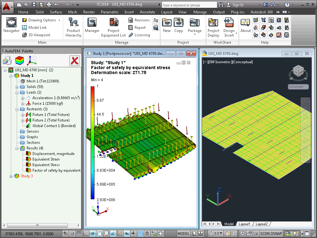
Verlagerungen eines Schiffes Einheit mit Seilen angehoben


Sicherheitsfaktor von der angehobenen Schiffsstruktur
Diese Funktion ist bei Vorhandensein einer Lizenz für das Modul zur Integrierung mit ShipConstructor verfügbar und ermöglicht es dem Nutzer, durch einen Klick eine laminare FEM-Approximation des ursprünglichen dreidimensionalen volumigen Konstruktionsmodells, das im ShipConstructor konstruiert wurde, zu erhalten.

Dialog mit einer Auflistung der wesentlichen Möglichkeiten des Moduls zur Integrierung mit ShipConstructor
Die wesentlichen Vorteile der vorliegenden Herangehensweise für die Analyse von überdimensionalen Schichtkonstruktionen sind:
• Deutlich angemessenere Anforderungen an die verfügbare Rechenleistung bei der Analyse von überdimensionalen Schiffskonstruktionen. Wobei im Falle einer Erstellung von einem adäquaten FEM-Modell die Gültigkeit vom Rechenergebnis mit den allgemein üblichen Methoden übereinstimmt, welche für die Analyse von Schiffsbaukonstruktionen verwendet werden.
• Die relative Einfachheit in dem Erstellen vom FEM-Modell, Rechengitter und der Eingabe von Grenzbedingungen.
• Die Möglichkeit der manuellen Bearbeitung von FEM-Aufgaben zur Bewerkstelligung der Möglichkeit für den Erhalt von einem möglichst adäquaten und gültigen Ergebnis.
Neue Möglichkeiten des Postprozessors
Verbesserung der Befehle zum Erstellen von "Sensoren" und anwenderspezifischen Koordinatensystemen
Bei den Befehlen zum Erstellen von anwenderspezifischen Koordinatensystemen wurde die Möglichkeit zur Erstellung von mehreren Sensoren oder Koordinatensystemen durch einen Befehlsaufruf hinzugefügt. Im Dialog gibt es jetzt den Button  , der es ermöglicht die aktuelle Objektbestimmung zu speichern und zur Erstellung des nächsten überzugehen, ohne den Dialog zu verlassen. Dies beschleunigt erheblich den Arbeitsprozess, insbesondere bei großen Modellen.

Erstellung von mehreren Sensoren durch einen Befehlsaufruf

Erstellung von mehreren anwenderspezifischen Koordinatensystemen durch einen Befehlsaufruf
Sensorengruppen
Der neue Befehl ermöglicht es, eine Sensorengruppe auf einmal zu erstellen, welche auf einer geraden Linie liegt. Die erstellte Sensorengruppe kann zur Erstellung der Ergebnisgrafik verwendet werden. Der Benutzer muss die Gesamtzahl an Sensoren und die äußeren Modellpunkte oder Koordinatensysteme, zwischen welchen die Sensoren liegen müssen, angeben.

Die Sensorengruppe ermöglicht es, die Punkte für den Erhalt von Daten zur Grafikerstellung zu bestimmen

Ergebnisgrafik, erstellt anhand der Sensorengruppe
Neuer Dialog vom Ergebnis "Reservekoeffizient"
Es wurde grundlegend die Funktionslogik des Befehls zur Einstellung vom Ergebnis "Reservekoeffizient" überarbeitet. Der neue Dialog ermöglicht es flexibel und anschaulich die Stufen der zugelassenen Belastungen zu bearbeiten, welche zur Festigkeitsprüfung der Konstruktion verwendet werden. Im Dialog wird für jedes Detail die zur Berechnung verwendete zugelassene Belastungsstufe angezeigt. Der Benutzer kann vereinzelte Details aus der Berechnung ausschließen, anwenderspezifische Werte zugelassener Belastungen eingeben, Messeinheiten ändern.

Der neue Dialog der Ergebnisparameter Reservekoeffizient unter Belastungsbedingungen
Verbesserung der Bedienoberfläche
Die Taste F1 ruft die Hilfe aus der AutoFEM-Funktionsleiste auf. Es wurde die Möglichkeit zum Öffnen der Kontexthilfe auf Knopfdruck der Taste F1 beim Heranführen mit Maus auf den Button in der Funktionsleiste der Hauptbefehle von AutoFEM Analysis realisiert.

Neue Lektion in den AutoFEM Tutorials
Bei der Sammlung von Lektionen in AutoFEM Analysis wurde die Lektion zur Arbeit mit dem Pre- und Postprozessor des Systems hinzugefügt, welche Schritt für Schritt und an Beispielen zeigt, wie man die Eigenschaften der Fenster vom Pre- und Postprozessor einstellt, Sensoren, Koordinatensysteme erstellt, Ergebnisgrafiken konstruiert usw. Außer der schrittweisen illustrierten Anweisung umfasst die Lektion ebenso einige Videos, welche die wesentlichen Arbeitsmethoden demonstrieren.

Lektion zur Arbeit mit dem Pre- und Postprozessor von AutoFEM Analysis
New features of AutoFEM Analysis 2.8
Support of AutoCAD 2016 and ShipConstructor 2016
Version 2.8, AutoFEM Analysis is compatible with the nine different versions of AutoCAD, namely: AutoCAD 2007-2010 and 2012-2016 which all work in the Windows XP/Vista/7/8 environment
AutoFEM Analysis Installer is improved
An installation of compulsory program components (Microsoft Visual Studio redistributable packages) was added to the AutoFEM Analysis Installer, which was necessary to make the system work. The installer determines which version of AutoCAD and offers to the user the installation packages necessary to work with the given version of AutoCAD.
The dialogue of installation of the necessary Microsoft components
Dialogue of program launch
The application launcher was improved. In particular, on default, the mode of AutoFEM launch as "autoload" is installed now (i.e. the download of AutoFEM into AutoCAD together with the each AutoCAD launch)
In addition, all actions to set up the licence and manage the work with licences, such as "Activation/deactivation" of the licence, are available now from the start dialogue after pressing the button "Configure licence" (previously, they were only accessible from the Windows menu).
Dialogue of managing the licence type (server-side or local one) and of activation/deactivation of the licence
New functionalities of the Preprocessor
Using Progress bars when fulfilling operations of data processing
Most operations which take long time to be fulfilled in the case of large models (for instance, acquiring the model from AutoCAD in the process of creating the set of bodies for FEA) now use Progress bars which visualize the current stage of the program work and allow one to estimate the remaining scope of work before the end of the operation. The Progress bar reflects the number of the already worked-through objects and allows one to indirectly estimate the time necessary to complete the current stage.

Progress bars illustrate the current state of acquisition of the 3D model from AutoCAD
Dialogue of the command " Set of Objects for FEA" is improved
The ability to manage the smoothness of the imaging of cylindrical and spherical surfaces in the Preprocessor window is now added at the primary acquisition of the 3D model geometry from AutoCAD. The special slider allows the user to set a desirable minimum accuracy of approximation of curved elements of the 3D model.
A cylinder of small diameter is approximated as an octagon
A more accurate approximation of the same cylinder by a polygon with 24 segments
New abilities for the command “Diagnostics of the Study”
Excluding dangling bodies from the calculation
The command “Study Diagnostics” has acquired the ability to exclude dangling bodies and groups of bodies from the calculation without their withdrawal from the study. "Dangling” parts mean single parts or small groups of parts which do not make contact with other parts of the 3D assembly, i.e. those which appear to “hang” in the air. Such objects would not directly contribute to the mechanical strength computations, if not attached in some way they would fly to “infinity” when forces were applied to them. This option makes it possible to perform the strength calculation, even if there were multiple, separately located unfixed objects present in the 3D model (and they might be overlooked).
Dangling bodies are marked in green in the Preprocessor window
New abilities for the mesh generator
Accurate workings with Multi Volume objects
The new version of the mesh generator permits the use of so-called multi volume bodies in the studies (i.e. bodies comprised of several different volumes without points of contact between them). It significantly simplifies the preparation of the computation model in the case of the presence of multi volume bodies. In the previous versions of AutoFEM, the presence of multi volume bodies was an insurmountable obstacle in the way of creating a finite-element mesh.
Diagnostics of a 3D model with multi volume bodies as per previous version
Presence of multi volume bodies is now no hindrance to creating a finite-element mesh
Improvements in working with ShipConstructor
Efficient working with large models in ShipConstructor
Due to the improved working of some functions of AutoCAD, starting from the version of AutoCAD 2015 and especially AutoCAD 2016, AutoFEM Analysis now is able to efficiently process very large assembled 3D models of ShipConstructor, usually containing thousands of 3D models of parts.
AutoFEM Analysis can now process assemblies containing thousands of objects, including the hulls of sea vessels
Improvements to the module of integration with ShipConstructor
The option of acquiring specific geometry like that of ShipConstructor was improved. We mention the specific geometry parts which cannot be selected for FEA analysis by standard means using AutoFEM, because they have a specific type, which does not coincide with the type of 3D solid in AutoCAD. This option, in particular, allows one to obtain the curved geometry of the underwater parts of sea vessel hulls, pipeline parts and to manage the list of obtained objects.
The improved dialogue of integration with ShipConstructor
Working with the hulls of sea vessels
An entire set of dedicated tools for working with hull parts of sea vessels was specially developed to satisfy the needs of shipbuilding engineers who use ShipConstructor. We recommend that laminar finite-element representations of calculated models, created on the basis of 3D solid-body models of designs are used as the main technique for strength analysis of solid hull units of sea vessels.
Version 2.8 offers these dedicated set of tools, providing the ability to create studies with the hulls of sea vessels, with an account of the specific representation of these designs, which are used in ShipConstructor.
Creating studies with hull-like objects
The curved hulls of sea vessels in ShipConstructor are represented with the help of objects of special type. For these purposes, the class of objects (SCONCURVEDPLATE) is created, representing the curved geometry as the aggregate of triangular or rectangular facets which have the width. In the course of acquiring a 3D model from AutoCAD, AutoFEM Analysis 2.8 correctly unites the aggregates of these facets in a single, uniform facet, which makes it possible to set boundary conditions, applied to these elements of the design.
The hull of a sea vessel in the window of AutoCAD/ShipConstructor
The hull of a sea vessel in the window of the Preprocessor of AutoFEM Analysis
Application of distributed loads to hulls of sea vessels
When creating a study in the laminar finite-element setting, the system automatically groups the facets, describing the geometry of a sea vessel hull, in a generalized face that allows one, in one click, to choose these design elements in order to apply the distributed boundary conditions to them (pressure, force and so on).
Applying the load “Hydrostatic pressure” to elements of a ship’s hull
Setting boundary conditions for chains of edge segments
When working with finite-element models based on plates, the boundary conditions are applied to facets and edges. The dedicated tool set allows easier application of the boundary conditions to edges and, thus, for the selection of a set of segments of one edge by stating the first and last (or next) segments. The system automatically adds all intermediate segments belonging to a single body. This functionality makes it possible to apply boundary conditions to the edges of hulls, containing a few or hundreds of separate segments.
Selection of a chain of edge segments for setting a boundary condition
Setting boundary conditions for the curved surfaces of hulls
Concerning the loads applied to facets (force, pressure, torque, bearing load, and additional mass), there is a new option to select, in one click, the complete surface of the part, even if it is divided into multiple facets. This is typical of units of the hull type, created in ShipConstructor. In a special dialogue window, the user sets out the permissible deviation from the normal (in degrees), based on which the system will automatically select facets, whose deviations from the normal are no greater than the set value, and applies the boundary condition to all the aggregate of the facets by one click.
Automatic selection of the curved facet of a unit, approximated from many facets
A new approach to modelling thin-wall designs
Automatic transformation of a volumetric finite-element study into laminar one
Most typical designs in the shipbuilding industry (construction of sea vessels and coastal facilities) 90-95% of them are made of steel sheets and profiles. It is generally known that the finite-element analysis of such designs using 3D finite elements (such as tetrahedrons or hexagons) is often hard to produce from the computational stand (i.e. they require too many computational resources). In the theory and practice of finite-element computations, it is generally acceptable to use finite elements of plates (shells) of triangular or rectangular shape for the estimation of the tension state of such designs.
In version 2.8, the dialogue used for creating the study, visually reflects the selection of a finite-element setting (3D or laminar), in which the user wishes to create a finite-element study. For modeling solid designs of ships, which are mostly fabricated from sheet metal parts, we recommend that finite-element modelling by laminar elements is used.
Choice of the option for creating a shell study from a solid-body 3D model
In AutoFEM Analysis 2.8, an intellectual algorithm is implemented, which allows one to automatically build the computational model using triangular finite elements of plates for designs made of 3D solids.
The logic of the algorithm is that all elements of the design can be considered as laminar parts. The system analyses the geometry of the part and automatically selects the part surface with the greatest area to be included in the computation. When selecting the facets of the 3D solid, the mutual location of the part relative to other contacting parts is taken into account. As a rule, a facet with the greatest number of contacts with the neighbouring parts is selected for computation. The system will automatically determine the width of the laminar part. The user can change both the automatic selection result (i.e. select or add another facet in the computation) and the width assigned to the specific part by the system. This allows the computer to flexibly adjust the laminar finite-element model, while striving for the greatest degree of correspondence in the calculated model to its solid-body original prototype. In the process of the automatic construction of the equivalent laminar model, the system analyses the mutual location of the design’s parts and provides for a better preservation of the topology of the entire design, that means that parts in contact in the initial solid-body 3D model will, as far as it is possible, remain in touch in its laminar approximation. The user can manage this process, switching on or off the option called "Restore topology of the structure" in the dialogue of creating the study. The same dialogue sets options for automatic unification of facets in the uniform facet and for a threshold of the permissible number of facets for the automatic selection of the geometry to be included in the study.
Options of the command of creating the shell finite-element study, based on facets of 3D solids
Displacements of a vessel unit lifted with ropes
Factor of safety of the lifted ship structure
This functionality is available together with the licence for the module of integration with ShipConstructor and allows the user to obtain in one click the laminar finite-element approximation of the initial 3D volumetric model of the design built in ShipConstructor.
The dialogue listing basic functions of the SC integration module
Considering the analysis of large-size sheet designs, the main advantages are as following:
• Much less severe requirements of the available computational possibilities when analysing large-size ship designs. Though, in the case of building an adequate finite-element model, reliability of the computational result corresponds to common techniques, used to analyse designs usual for shipbuilding.
• Relative simplicity in building the finite-element model, computational mesh and the setting of boundary conditions.
• The possibility of editing manually the finite-element study to achieve the most acceptable and reliable result.
New possibilities for the Postprocessor
Improvement of commands in creating sensors and user-oriented coordinate systems
The commands for creating sensors and user-tailored coordinate systems now have the ability to create several sensors or coordinate systems while the command is retrieved once. The dialogue has a new button, , which allows one to save the current definition of the object and go on to the creation of the next object, not dropping out of the dialogue. It significantly accelerates the work, especially concerning large models.
Creation of several sensors with one click of the command
Creating several user coordinate systems with one click of the command
Group of sensors
This new command allows one to create a group of sensors, positioned along one right line, in one click. So the created sensor group can be used to construct a graph of the result. The user must specify the total number of sensors and limits of the model or coordinate systems, in-between which the sensors are located.
The Group of sensors allows the user to define points for obtaining data to plot a graph
The graph of the result, drawn on the basis of the sensor group
New dialogue of the result, called “Safety Factor"
The logic of work of the result tuning command "Safety factor " was radically reorganised. This dialogue allows one to flexibly manage and produce a visual of the levels of permissible stresses, used to test the designs for strength. In the dialogue, the level of permissible stress is shown for each part. The user can exclude separate parts from the computation, set user values of permissible stresses and change units of measurement.
The new dialogue of result parameters “Safety factor” in terms of stresses
Improvement of the User Interface
The button F1 calls reference for the command from the AutoFEM ribbon. The possibility of opening the context reference using the button F1 (the mouse is directed to the button) in the ribbon of AutoFEM Analysis basic commands.
A new lesson in AutoFEM Tutorials
The training course of AutoFEM Analysis now includes a lesson for working with the Preprocessor and Postprocessor of the system, showing a step-by-step guide and illustrating how properties of Preprocessor and Postprocessor windows can be tuned, sensors and coordinate systems can be created, graphs of results can be constructed, etc. In addition to a step-by-step illustrated manual, the lesson contains several videos demonstrating the basic methods of work.
Lesson for working with Preprocessor and Postprocessor of AutoFEM Analysis
AutoFEM Schulung
Ein Gelenk - AutoFEM Software & NDAR - AutoFEM Trainingskurs findet in NDAR Büro (Antibes, Frankreich)
am 31 März-02 April 2015.
Der Kurs findet in Englischund anderen Sprachen werden unterstützt (Französisch, Italienisch).
Der Kurs ist für Anfänger und Fortgeschrittene Nutzer des Programms und Interessenten FE-Strukturanalyse. Betroffenen Materialien umfassen:
- Programmumgebung und GUI, Einstellungen
- Arten von Studien
- Vorbehandlung: Vernetzung, Randbedingungen, Materialien
- Benutzer-Koordinatensysteme
- ShipConstructor integration
- Verarbeitung, Gleichungslöser-Typen
- Nachbearbeitung: mit Sensoren, Graphen, Diagramme Farbe, führen Probenahme, berichtet
Eine AutoFEM-Lizenz wird während des Kurses kostenlos bereitgestellt. Mitbringen sollten ihre Laptops, die AutoCAD laufen sollte (Hinweis AutoCAD 2011 wird nicht unterstützt). Obwohl Ausbildung Modelle zur Verfügung stehen, werden Teilnehmer ermutigt, ihre Modelle bringen um praktische Arbeiten ihre eigenen Projekte. Anmeldung akzeptiert werden auf einer ersten kommt, mahlt zuerst-Basis, Plätze begrenzt sind.
Alle Kursteilnehmer haben Anspruch auf 20 % Rabatt beim Kauf der Software.
Kontaktieren Sie für weitere Informationen oder Logistik-Fragen bitte Diese E-Mail-Adresse ist vor Spambots geschützt! Zur Anzeige muss JavaScript eingeschaltet sein!.
Wir freuen uns auf Ihren Besuch auf dem Platz,
Ansprechpartner:
Stéphane DARDEL. Nick DANESE
Systeme & Technologien ™
150 rue de Goa, 06600 Antibes, Frankreich
Tel + 33-4-9291 1324 / fax + 33-4-9291 1338
Diese E-Mail-Adresse ist vor Spambots geschützt! Zur Anzeige muss JavaScript eingeschaltet sein! / www.ndar.com

New features of AutoFEM Analysis 2.2
Integration with ShipConstructor
Based on AutoCAD, ShipConstructor is the leading software product for ship design and ship building, adopted worldwide. ShipConstructor provides the tools needed to design, model and prepare production documentation for any type of vessel, be it a ship, a submarine or an offshore platform.
In the course of designing a vessel or an offshore structure, it is necessary to verify its strength and stiffness characteristics, preferably using Finite Element Analysis. Thanks to direct integration of AutoFEM Analysis and AutoCAD, ShipConstructor users can now use AutoFEM to transparently run FEA analysis of ShipConstructor models.
As of AutoFEM Analysis v2.2, the integration with ShipConstructor is complete. The ShipConstructor 2014 stock catalogue supports the mechanical properties of materials needed for FEA, and AutoFEM reads the full model topology directly, including:
• Names of parts
• Names of AutoCAD layers (for parts in the current document)
• Data about the material (name, grade, etc.). If the user has not specified thee, they will be taken from the native AutoFEM Analysis materials library, using a name matching technique.

Settings of integration with ShipConstructor
ShipConstructor parts and all related information are acquired by AutoFEM Analysis, and
if needed, ShipConstructor materials are name-matched with materials in the AutoFEM library.
Calculation example of a ShipConstructor Assembly
More information about joint work of AutoFEM & Shipconstructor can be found here:
AutoFEM Analysis & ShipConstructor Software: Working Together
or here
AutoFEM Analysis & ShipConstructor Software: Working Together (pdf)
Work with the AutoCAD blocks
The new version of AutoFEM Analysis allows the user to work more effectively with AutoCAD blocks. In the process of creating a set of objects for the finite-element analysis, the system analyzes the content of the block and processes each object contained in the block as the individual solid body. Then, each element of the block may have its own material, and one may even carry out an individual analysis for each solid contained in the unit. It is also possible to activate the single-body mode for the unit. In this case, the collection of parts will be considered as one, and the selected material used for all the components (parts).

Processing the group of parts as a unified solid-body object

Calculation example: the block is considered to be one solid body

The block is analyzed as the aggregate of the several bodies composing it,
which were created in AutoCAD
New utility of setting up "FEMA Tool"
Launch of AutoFEM Analysis from the Start menu. The AutoFEM Analysis utility "FEMA Tool" has been completely redeveloped, and AutoFEM Analysis can now be launched directly from the All Programs|Windows menu. In the dialogue, the user chooses the AutoCAD version using which he or she wishes to launch AutoFEM Analysis.

Shortcut for launching AutoFEM Analysis from the All Programs Windows menu

Dialogue hosting the configuration and launching of AutoFEM Analysis
In the "FEMA Tool" utility dialogue, one selects the version of AutoCAD in which to run AutoFEM Analysis, and identifies the licence server by its network address.
Materials: new possibilities
Material parameters shown in user defined units (other than SI)
The materials library now documents the physical properties of materials, in the user-selected system of units. The user-selected unit system is stored by the system and remains available thereafter.
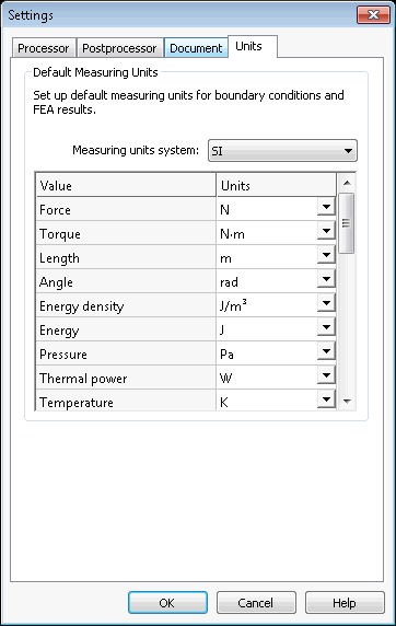
Choosing the unit system
Copying materials
Materials can be copied within the user library. The copies can then be edited to obtain new materials with new physical properties.

Copy of materials and user defined units are available
New ways to work with AutoCAD layers
Using AutoCAD layers for grouping objects within the Study
Objects included in the Study are grouped by layer and identified in the list by the name and colour of the layer.
Objects in the Study are grouped by layer
Assigning the material by layer
It is now possible to assign a material in one step to all solids placed in the same layer.
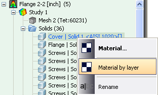
New command "Material by layer"
Assigning the thickness of plate parts by layer
It is now possible to assign a thickness to all structural shell parts located on the same layer.

New command "Thickness by layer"
New methods of creating coordinates systems
The command used to create a user coordinate system has been greatly improved.Along with the ability to import coordinate systems from AutoCAD, it is now possible to create and orient the coordinate systems, selecting vertexes of the 3D model in the Preprocessor window.
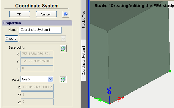
Use of the 3D model vertexes to define the UCS
New options to generate a tetrahedral mesh
Two new options have been added to the command used to generate tetrahedral meshes:
Do not create elements which are too small. This option allows restricting the generation of small finite elements in order to decrease the total number of elements and cut the number of the problem dimensions without prejudice to the calculation accuracy. This option is activated by default.
Remove erroneous tetrahedrons.This option automatically removes poor quality tetrahedrons during mesh creation,thereby avoiding the need for geometrical corrections during calculation runs. This permits a more reliable transfer of calculation results from one study to another (for instance, to transfer the results of thermal analysis to static analysis for calculation of thermal elasticity). This mode is activated by default.
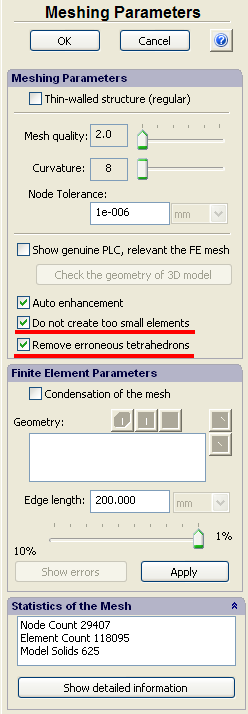
New options of mesh generator
New selection tool to identify objects located in one plane
A new selection tool analyses boundary conditions and finds all the objects lying in one plane. First, one selects the entities of 3D model (facets or two edges located in one plane, or three vertices). Then, using the new selection button, all the coplanar objects from that selection (facet, edge, or vertex) are selected and grouped. This possibility essentially facilitates the preparation of the finite-element model of large assembly structures, consisting of hundreds or thousands of parts.
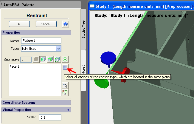
Select the first facet

All facets lying in the same plane as the first selected facet
are automatically added to the list when pressing the button
New boundary condition – Plane of Symmetry
This command allows to define the planes of symmetry of a structure, i.e. the planes relative to which the structure’s deformation is supposed to be symmetrical. As a rule, the planes of symmetry are used to cut the dimensionality of a problem being solved, at the expense of the possibility of analysing only one part of the structure. At that, the multiple (at least by 2 times) decrease in the number of algebraic equations (at the same level of discretization) is achieved.

Dialogue of the Plane of Symmetry command

Calculation example: use of symmetry to decrease the problem
New report generation dialogue
Working with the report generation dialog has been made much easier. Management of the output results has been streamlined, and the creation of the 3D VRML model, used to display results, has been improved. By default, the VRML model will not be created if the number of finite elements exceeds 50,000. The user is able to set the threshold value.

New dialog of Report settings
Creation of VRML models of results has been improved
Generating VRML models of results is now optimized as function of visibility.

Non-linearity in static problems for models based on AutoCAD Surfaces
Support of geometric non-linearity now possible for static analysis using shell finite elements.
")
Geometric non-linearity is supported using plate finite elements (shells)
Calculation info
A Study Properties page documenting the result of the latest successful calculation has been added, a very useful reference.
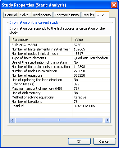
New tab Info contains main information about the solved study
Attention!
If while opening the DWG file, containing the saved studies of previous AutoFEM version, you see the AutoCAD error messages, remove the previous data of AutoFEM Analysis with the help of the command _FEMAERASEALL  and recreate the studies.
{source}
<script src="https://apis.google.com/js/platform.js"></script>
<div class="g-ytsubscribe" data-channelid="UCE62j8F63nM3QX5gsQj0Grg" data-layout="full" data-count="hidden"></div>
{/source}
Neuen Funktionen von AutoFEM Analysis 2.5
Die Zusammenarbeit mit AutoCAD 2015 und ShipConstructor 2015
Beginnend mit der Version 2.5, ist AutoFEM Analysis mit acht verschiedenen Versionen von AutoCAD, nämlich kompatibel: AutoCAD 2007-2010 und 2012-2015, die Arbeit in der Windows XP / Vista / 7/8-Umgebung.
AutoFEM interface language selection
Beginnend mit der Version 2.5 kann der Anwender die Software in einer von fünf europäischen Sprachen zu starten: Englisch, Deutsch, Französisch, Italienisch oder Spanisch. Per Default verwendet das System die Sprache der AutoCAD, in dem es gestartet wird.

Dialogfenster von AutoFEM Spracheinstellungen

Die gewählte Sprache wird in der AutoFEM gezeigt starten Dialog
Verbesserter Dialog des Befehls "Satz von Objekten für FEA"
Maßeinheiten der Länge. Nun kann der Benutzer die Längeneinheiten des 3D-Modells nicht nur in den Dokumenteinstellungen, sondern auch direkt in den Prozess der Erstellung einer Reihe von Objekten für FEA gesetzt. Im gleichen Dialog kann der Anwender die Einheiten ändern. Per Default sind die Einheiten stimmen mit AutoCAD Einheiten des aktuellen DWG-Datei.

Maßeinheiten können beim Erstellen der Menge von Objekten für FEA definiert werden
Nachrichten über ShipConstructor Integration
Unterstützung der speziellen Geometrie wie Rohre. Die Optionen des ShipConstructor Integration wurden geändert. Eine neue Möglichkeit, von der ShipConstructor Dokument eine bestimmte Geometrie laden (wie Rohre) wurde hinzugefügt.

Option des speziellen Geometrie Import

ShipConstrutor Rohre im Preprocessor Fenster

Gelöst Studie mit Rohren
Neue iterativ Frequenz / Knicklöser
In AutoFEM 2,5, wird eine neue Frequenz und Knicken Löser dargestellt. Direct (Lanczos Algoritm) und Iterative - Jetzt kann der Anwender zwischen zwei Methoden zur Lösung dieser Probleme zu wählen.
Direkt (Lanczos Algorithmus) verwendet eine vollständige Inversion der Matrix, um die Frequenzen zu finden, daher ist es erfordert in der Regel mehr Speicher als der iterativ Verfahren. Es funktioniert ziemlich schnell, relativ kleine Probleme auf leistungsfähigen Computersystemen zu lösen.
Iterative Löser hat die untere Speicheranforderungen als das direkte Verfahren, da die Umkehrung der Matrix nicht erforderlich ist. Daher ermöglicht es uns, große Frequenz / Knick Probleme zu lösen. Das Volumen von Studien ist nur durch die Berechnungsfunktionen des Computersystems, (zunächst verfügbaren RAM und ROM) begrenzt.

Neue Dialogfenster des Frequenzlöser

Neue Dialogfenster des Knicklöser

Einstellung einer neuen Frequenz / Knick iterative Solver
Auf der Suche nach Frequenzen im Bereich
Die Möglichkeit, Resonanzfrequenzen zu suchen innerhalb des definierten Frequenzbereich bereitgestellt wurden. Der Benutzer sollte die niedrigsten und höchsten Frequenzen und die Anzahl von ihnen gefunden werden soll. Das System Resonanzfrequenzen in dem angegebenen Bereich zu suchen.

Der Dialog der Intervallfrequenz Löser
Gemeinsame FE-Netz für mehrere Studien
AutoFEM ermöglicht dem Benutzer die vorhandenen Studien zu kopieren und dann Benutzer kann eine Kopie als Basis für einen neuen Finite-Element-Studie zu verwenden. Seit der Version 2.5, hat der Anwender die Möglichkeit, auszuwählen, ob der ursprünglichen Studie und seine Kopie haben eine gemeinsame (single) Finite-Elemente-Netz, oder wenn sie unabhängig sind. Auf Standardeinstellung bietet das System eine unabhängige FE-Netz für die Kopie der Originalstudie.

Dialog zur Auswahl der Modus der Befehl "Kopieren"
Neuer Service Befehl «Physikalische Eigenschaften"
Dieser spezielle Befehl ermöglicht es dem Benutzer, die Werte der Volumenmasse-Eigenschaften der ausgewählten Objekte (Feststoffe oder Oberflächen) erhalten. Der Befehl ist im Kontextmenü für das ausgewählte Objekt im Baum des Studiums oder im Preprocessor Fenster. Der Befehl berechnet Volumen / Fläche / Masse (wenn das Material zugewiesen wurde) der Finite-Elemente-Darstellung der Originalobjekte und vergleicht diese ursprünglichen Parameter mit von AutoCAD-Funktionen für den ursprünglichen AutoCAD-Geometrie berechnet den gleichen Parametern. Die Differenz zwischen diesen Werten hilft Schätzung der Genauigkeit der Finite-Elemente-Darstellung des simulierten Struktur.

Abrufen der Befehl "Physikalische Eigenschaften"
Je nach der für die Finite-Elemente-Studie gewählten Geometrie sind drei Arten der Ergebnistabelle zur Verfügung.

Tabelle der Volumenmasseeigenschaften der Studie anhand von 3D-Solids
Neue zusätzliche Möglichkeit, 3D-Modell-Diagnose
Der Modus "Finden verdächtige Geometrie". Dieser Modus ermöglicht es dem Benutzer, um sehr kleine Einheiten des 3D-Modells, wie extrem kleine Schritte, Filets oder Fasen, der die erfolgreiche Schaffung des tetraedrischen FE-Netz (die Netzgenerator kann nicht in Tetraeder teilen sie) verhindern kann zu finden. Wenn das Netz nicht erstellt wird, sollten Sie diese Elemente der Geometrie ändern, um Fehler zu beseitigen. Das Seitenverhältnis definiert den Schwellenwert, wenn das Objekt kann als ein fehlerhaftes Objekt betrachtet werden.

Sehr kleine Stufe
Neue Zugang zum AutoFEM Materialbibliothek
Der Zugang zum AutoFEM Materialbibliothek erleichtert worden. Jetzt kann der Anwender Bibliothek von Materialien durch drei Arten öffnen: mit Haupt AutoFEM Menü AutoFEM Band oder die Schaltfläche eines schnellen Zugriff auf die Spitze der AutoFEM Palette.
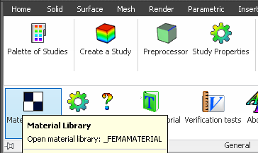
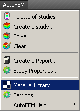
Neue Wege der Zugang zum AutoFEM Materialbibliothek
AutoFEM Hilfe in der spanischen Sprache
Vollständiger Text und Kontext abhängig Hilfe ist jetzt in der spanischen Sprache zur Verfügung.

AutoFEM Hilfe in der spanischen Sprache
Neue Lektion über AutoFEM & ShipConstructor Integration
A special interactive lesson on the theme of AutoFEM & ShipConstructor Integration has been added in AutoFEM Tutorials.

Neue Lektion über gemeinsame Arbeit mit ShipConstrutor
Viele andere kleine und mittlere Verbesserungen realisiert.
Wichtig! Bitte lesen Sie vor dem Upgrade von der kommerziellen Version.
Um die Lizenz 2.x auf 2.5 zu übertragen, müssen Sie die Lizenz 2.2 vor der Deinstallation der Software zu deaktivieren. Dann löschen Sie die vorherige AutoFEM Version installieren AutoFEM 2,5 und aktivieren Sie die Software neu mit der gleichen Seriennummer. Um die Lizenz zu deaktivieren, verwenden Sie einen speziellen Befehl in der AutoFEM Ordner.

Menüpunkt "Deaktivieren Licence"
AutoFEM Analysis 2.0 build 5670 (9. Oktober 2013)
Des Problems öffnen Sie DWG-Dateien von Windows zu erforschen oder aus Erfahrungen der AutoFEM Analysis Tutorial, während AutoCAD nicht funktioniert, wird eliminiert.
In der Versammlung des AutoFEM Analysis 2.0 datiert Build 5669 17 Sep 2013, Dateien, die DWG mit Fehler wegen der verlangsamte Laden von AutoFEM Modulen geöffnet werden konnte. Dieses Problem äußert sich in der Assembly 5669, nur dann, wenn AutoCAD nicht bereits gestartet worden ist, während Sie einen Doppelklick in Windows zu erkunden, in der DWG-Datei mit den gespeicherten Daten der AutoFEM Analyse tun.
In Baugruppe 5670 wenn beim Öffnen einer Datei über die Windows-Suche unter Bedingung der nicht gestarteten AutoCAD, sehen auch die folgende Meldung Sie (es möglicherweise nicht angezeigt):
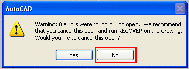
Es ist notwendig, das Verfahren zur Eröffnung weiter die -Dokument (drücken Sie "Nein"). Nach AutoCAD vollständig gestartet wird, werden alle Daten des AutoFEM für Arbeit zugegriffen. Alle Benutzer des AutoFEM Analysis 2.0 Build 5669 werden dringend empfohlen, das die Version sofort aktualisiert werden sollen; wie die Datei Format geändert wurde (früher erstellte Studien sind neu erstellt werden).