New features of AutoFEM version 1.5
New possibilities of the Preprocessor
Creating Studies
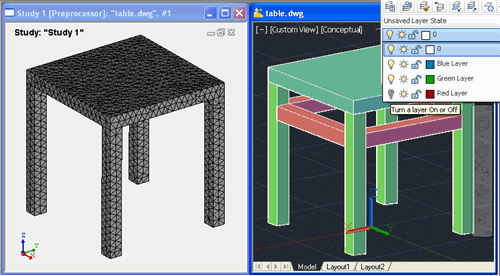
Working with AutoCAD layers. A new possibility to flexibly manage the composition of the bodies involved in the study has emerged, and AutoCAD layers are used to this end. Now only objects located on visible layers are added to the Study. Objects located on invisible (canceled) layers do not fall in the study.
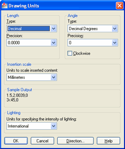
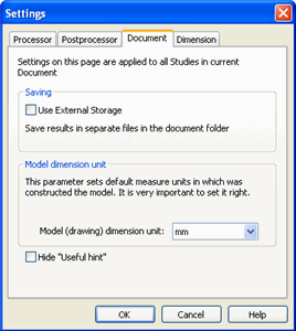
Draft dimensions. Now AutoFEM automatically perceives the geometric model in length units set up by the user in AutoCAD with the help of the UNITS command. Earlier, the dimensionality of a geometric model was set in AutoFEM regardless of AutoCAD. Besides, a new unit of length, feet, is added.
Naming bodies in the study. The order of identification of the bodies involved in the study is changed. Now, the name (unique for each study) is assigned to each body included in the study. When the composition of the study objects is changed, names of the bodies which are still included in the study do not change. This simplifies the discovery and correction of errors in geometric models in the studies.
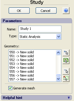
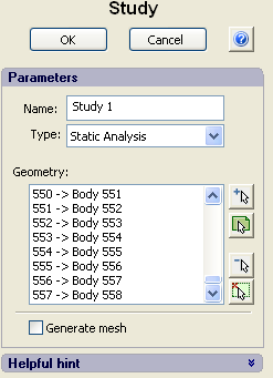
The new naming system of bodies in the study makes editing the study more convenient
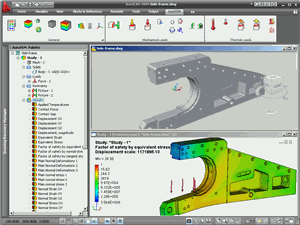
Promptitude is improved. The velocity of the work of the Preprocessor window is significantly improved concerning the opening of complex assembly models with a great number of solid-body objects (hundreds of parts). Geometrical data about the calculated model are now saved in file .dwg that speeds up the opening of the earlier saved studies.
Automatic correction of intersections. When the study is created, the check of body intersections is carried out. The matter is that no correct finite-element study can be created if the intersecting bodies are involved. In fact, at intersection of bodies, it happens that at one point in space, e.g., two different materials belonging to different bodies may be determined that is physically impossible. In previous versions of AutoFEM, the user had to remove the intersections manually, using AutoCAD commands. The new version is capable of launching the automatic removal of body “crosses” in the model.
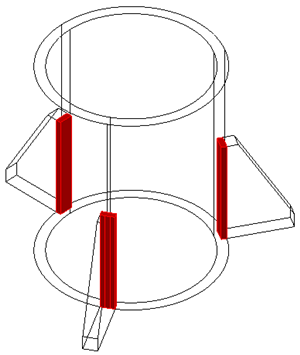
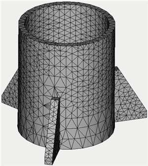
Removing the intersections for successful meshing
Study diagnostics. A new command, Study Diagnostics, is designed to help the user find erroneous objects in the study and test the correctness of a 3D model of a part from the point of the finite-element modeling on the whole. The command is performed automatically if the Preprocessor finds mistakes in the process of study creation. The following diagnostic modes are available:
- Mode Multi-volume bodies reflects multi-volume bodies if any in the study. The multiple-volume body is the term meaning the AutoCAD object which consists of several non-contacting volumes. Multi-volume bodies are perceived by AutoCAD as single object. One requirement set by the AutoFEM Preprocessor is the one-volume nature of solid bodies involved in the study, i.e. one closed area in the 3D space must correspond to a single body.
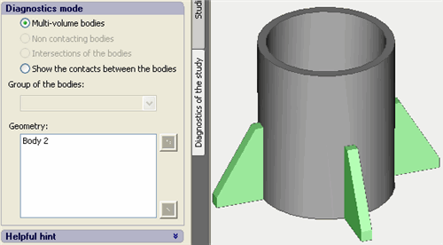
Image of the multi-volume body
- Mode Non contacting bodies reflects groups of bodies not having physical contact with other bodies. In some cases, the presence of independent groups of bodies in the study can indicate incorrectness of the problem setting.
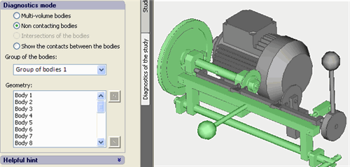
Non-contacting groups of bodies
- Mode Intersections of the bodies illuminates pairs of intersecting bodies. Creating the finite-element mesh for the intersecting bodies is not permitted. Actually, the read solid-body physical object does not permit the presence of more than one body and material at one spatial point
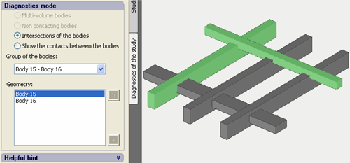
Reflecting pairs of intersecting objects in the diagnostics window
- Mode Show the contacts between the bodies reflects all facets by which the bodies contact with each other in the Preprocessor window. Using this command, you may check whether the determination of the body contacts by the Preprocessor is correct or not.
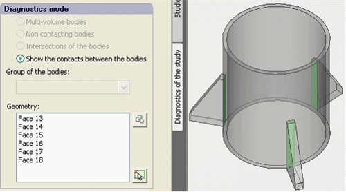
Parts in the model are joined by surface (shown green)
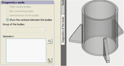
Surfaces of the contact are not revealed. The model’s correctness requires checking
Creating the finite-element mesh
The new dialogue of controlling the finite-element mesh generation. The new version of AutoFEM has a completely reworked interface of managing the generation of the finite-element mesh. Now the control over the mesh generator is performed using a special palette, similarly to the work of most other AutoFEM commands. The new interface allows the user to interactively manage the construction of the finite-element mesh, in particular, to set condensations on edges and facets of the models, as well as specify parameters of division for specific bodies. Command "Apply" generates the mesh but the dialogue of the command does not close at that. The user is able to estimate the mesh quality and return to editing its parameters when necessary.
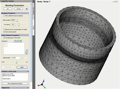
New interactive dialog of mesh generator
Management of parameters of the finite-element splitting. The new version has the capability to control the degree of finite-element splitting individually for different elements of a solid-body model. One can set the preferable length of the edge of a finite element near the specified set of edges, set facets or a 3D body.
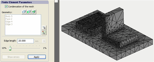
Using the tools of mesh condensation
The dialogue of statistics of the finite-element mesh. One may assess the mesh quality not only visually but using a special command, "Show detailed information", available in the dialogue of mesh generation control. This dialogue graphically reflects the quality of the shape of tetrahedron finite elements by several parameters.
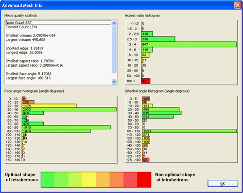
Detailed mesh statistics window
Visualization of erroneous objects. Sometimes, as a result of mesh construction, too flat tetrahedron elements are formed, with all four vertices lying in virtually one plane. Usually such elements can emerge at construction of a simplified mesh without control over the elements’ quality (mode Thin-walled structure, the Mesh quality set as "disable"). At the stage of pre-computed preparation, these elements are excluded from the set model. Now, if the model has such elements, button "Show errors" starts to be activated. When pressing it, erroneous elements are seen in the Preprocessor window. If such elements are too many, results of the calculation may be misrepresented; therefore, one should avoid too large a number of flat elements in the mesh model.
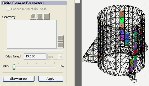
Erroneous finite-elements in Preprocessor window
New possibilities of the Postprocessor
The new report generator
The generator of html-reports on studies is completely reworked. Now reported are fuller data about study settings, boundary conditions, and materials as well as graphs and tables carrying data values from sensors. In addition, now the user can save a 3D result model as the report (in format vrml) while saving all color information about the result. To view the result in 3D, one should use the free off-site plugin, Cortona3D. The example of the report can be found by reference.
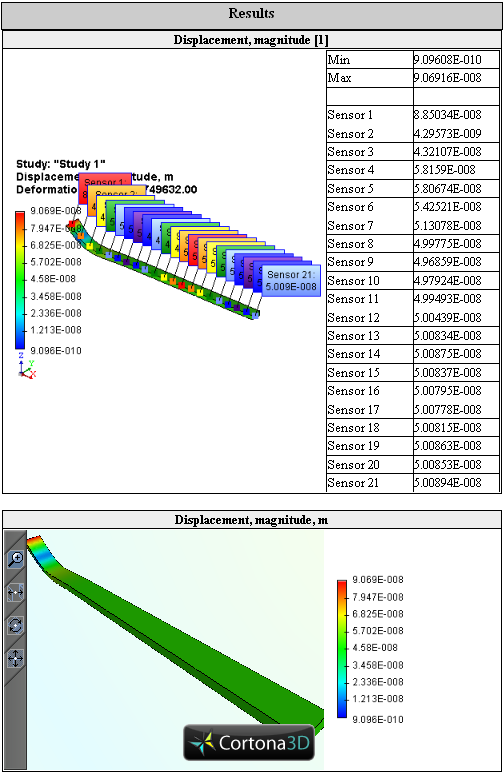
Sensors and 3D image of the result are included in study's report
Sensors
The sensor, which does not contain the result, e.g. does not lie on the model, is now marked by the red frame.
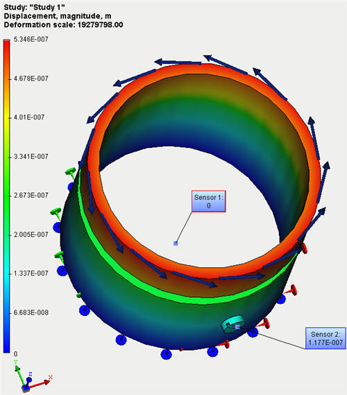
Sensor, marked by the red frame, does not contain the result
New features of AutoFEM 1.4, 1.3


