AutoFEM Fatigue Analysis
The AutoFEM Fatigue Analysis module is used in conjunction with AutoFEM Static Analysis and allows one to evaluate the strength of a structure, which is subjected to cyclic loading. This type of loading is usual in mechanical and structural engineering. The problem is that,when the load is constant, the strength of the structure load may prove to be sufficient. But if this load alternates frequently fatigue of the material occurs and the structure can be damaged or even crushed despite static analysis shows acceptable safety factor. The AutoFEM Fatigue Analysis module allows you to calculate the safety factor depending on the number of loading cycles and on the law of variation of the load's amplitude .

First, it is necessary to solve static study assuming that the loads are constant. Then the user can define cyclic loading parameters in dedicated dialog box of Fatigue Analysis Study. These parameters determine the type of loading (variation law) and number of cycles.
Before running Fatigue Analysis an S-N Curve for the material of the design should be determined. The special S-N Curve Editor is used for this purpose.

A total of 10 results is available in the Fatigue Analysis. They can be divided into four groups.
The group "Damage" includes the following results:
• damage by principal stresses;
• damage by equivalent stresses;
• damage by stress intensity;
The result is displayed in percentage and indicates the damage rate of the structure under the influence of cyclic stresses with the specified number and nature of loading cycles.
The group "Total Life" includes the following results:
• total life by principal stresses;
• total life by equivalent stresses;
• total life by stress intensity.
The result shows the minimum number of cycles Nmin, at which fatigue failure occurs.
The group "Factor of safety" includes results:
• factor of safety by the maximum principal stresses.
• factor of safety by equivalent stresses;
• factor of safety by stress intensity;
The group "Biaxiality". Biaxiality is the ratio of the smaller alternating principal stress (other than zero) to a larger alternating principal stress. The result characterizes inequality of amplitudes of principal stresses at the point and describes the spatial distribution of "unevenness" of the principal stresses in the volume of the body at every point. The value of biaxiality equal to 1 corresponds to the case of state of homogeneous stress? ?at the point.
Note that AutoFEM Fatigue Analysis module is also available in AutoFEM Analysis Lite.
Quick Start on AutoFEM Fatigue Analysis
Welcome!
 Welcome!
This lesson will help you to perform the fatigue analysis by the AutoFEM Analysis Lite package.
You will learn to:
 create a Fatigue Analysis study;
 specify a material; create a S-N curve and associate it with the material;
 define stress cycle parameters ;
 obtain calculation results in the form of colour plots.
Download demo video of the AutoFEM Fatigue Analysis Modul
Analyzing Results of the Static Analysis Study
Step 1: Analyzing results of the Static Analysis study
Let us analyze an model under the static load (i.e. it is necessary to perform calculation of the Static Analysis study) before performing the fatigue analysis.
The results of the Static Analysis study (equivalent stress and principal stress) will be used as stress amplitudes for performing fatigue calculation.
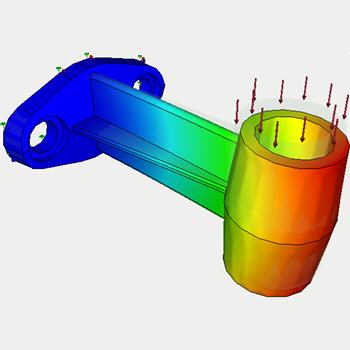
We will take sample model of the bracket and apply "Force".
Let us assume that the load is pulsating. We will try to estimate how many impulsive loading this bracket will stand if applied force is 110 kgf (or 1078.7315 N).
Firstly, we will suppose that the load is static (does not vary with time) and perform calculation of the static analysis study. This type of study has been considered into the Lesson 1 (see AutoFEM Static Analysis).
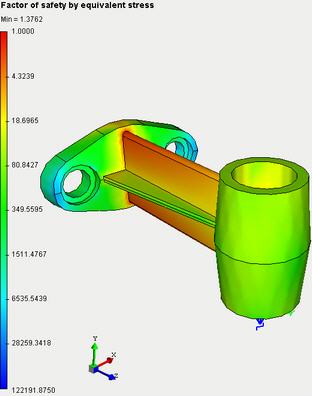
The results of this analysis are given below. Particularly we are interested in:
·factor of safety by equivalent stress (Kmin=" 1.3762);
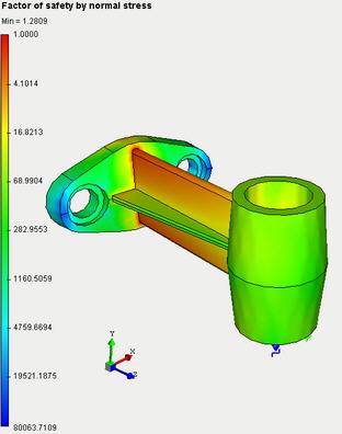
·factor of safety by normal stress (Kmin= 1.2809);
·factor of safety by shear stress (Kmin= 1.3052).
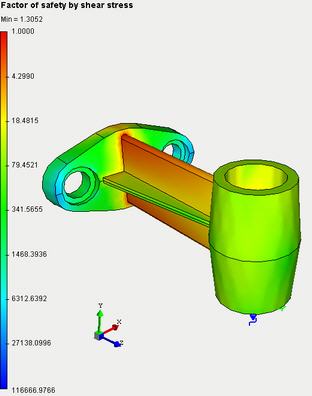
Minimum value of each factor is greater than 1, therefore the part will not fail under static load. Consequently there is sense to analyze this part under cyclically variable loads
Set S-N curve
Step 2: Set S-N curve
Fatigue Analysis requires presence of fatigue curve (S-N curve)for material. AutoFEM Analysis package provides a library of predefined S-N curves for some materials. S-N curve may be selected from the list of predefined curves of the libraryor may be createda new S-N curve in the editor of diagrams.
Tocreate the S-N curvethe user has to do the following steps:
1.Invoke the material properties window by choosing the solid in the service window "AutoFEM Palette" and performing the command "Material..."from the context menu (by pressing  ).
).
2.Provide a library of materials (into the group "Library").
3.Select the material ("Steel AISI 1020") from the list .
4.Press  .
.
5.Define the parameter "Name" and set the value "User defined" for the parameter "Hypothesis";
6.Create nodes for S-N curve with the following coordinates:
|
Number of Cycles |
Maximum Stress, Pa |
|
10 |
3.2592e+009 |
|
20 |
2.4188e+009 |
|
50 |
1.6993e+009 |
|
100 |
1.2845e+009 |
|
200 |
9.8468e+008 |
|
500 |
7".0990e+008 |
|
1000 |
5.5570e+008 |
|
2000 |
4.3727e+008 |
|
5000 |
3.4086e+008 |
|
10000 |
2.9545e+008 |
|
20000 |
2.4169e+008 |
|
50000 |
1.9096e+008 |
|
100000 |
1.6966e+008 |
|
200000 |
1.5254e+008 |
|
500000 |
1.3702e+008 |
|
1000000 |
1.2486e+008 |

7.Check the option "Assign this curve"
8.Press  in the dialog box of material properties.
Create Fatigue Analysis Study
Step 3: Create Fatigue Analysis Study
When you have done whatever is necessary it is able to perform the fatigue analysis successfully.
For creating the Fatigue Analysis study you need to:
1.Invoke the New problem's properties window using one of the following methods:
|
Command Line: |
FEMASTUDY |
|
Main Menu: |
AutoFEM | Create a Study... |
|
Icon: |
|

2.Select option "Fatigue Analysis" for parameter "Type";
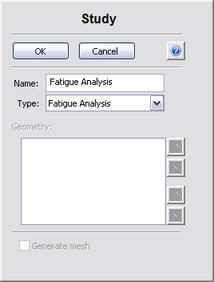
3.Press to confirm creation of the new study.
Set parameters of the fatigue cycle
Step 4: Set Parameters of Fatigue Cycle
For creating the fatigue cycle you need to:
1.Invoke the properties window of the fatigue cycle by choosing the group "Events" in the "AutoFEM Palette" windowand performing the command "Add..."from the context menu (by pressing  ).
).
2.Add already calculated static study;
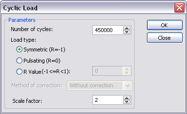
3.Set parameters of fatigue cycle : number of cycles (N =" 150000), "stress ratio (pulsating, R =" 0), "scale factor (1).
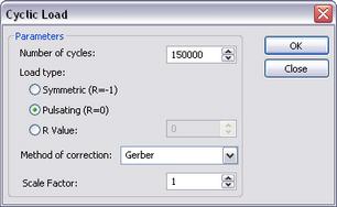
4.Press .
Solve Study
Step 5: Solve the Study
When every parameter of the fatigue cycle is defined it is possible to perform calculation.
Start solving by running appropriate command:
1.Invoke the solution's properties window by one of the following methods:
|
Command Line: |
FEMASOLVE |
|
Main Menu: |
AutoFEM | Solve... |
|
Icon: |
|

2.Press to start calculations.
Customizing Results
After successful completion of fatigue analysis calculation we may analyze the results to make conclusion on fatigue strength with the defined load cycles.
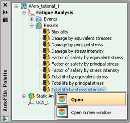
The list of results available for viewing is shown in the study tree in the folder "Results".
Use special dialog box to add or remove results from this list:
1.Press on the study name and run "Results..." command.
2.Select/deselect required items.
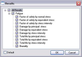
3.Press .
For viewing a result select it by pressing into the "AutoFEM Palette" window and run the command "Open". The result will be shown in a new window of the Postprocessor.
Analyzing Total Life
Step 6: Analyzing Results. Total Life
The total life plot shows that failure due to fatigue is likely to occur after Nmin number of cycles.
The table below shows that the bracket will stand the following number of loading cycles:
|
Total Life |
Number of cycles |
|
- by principal stress |
193825 |
|
- by stress intensity |
247566 |
|
- by equivalent stress |
428637 |
Thus we can see that minimum number of loading cycles that will break the part exceeds required number of cycles (150000) and we can make conclusion about part reliability at the specified cyclic load.
Analyzing the Damage
Step 6: Analyzing Results. Damage
The results for the damage rate indicate what percentage of the life of the model the specified event consumes.
|
Damage |
Damage Rate, % |
|
- by principal stress |
77.39 |
|
- by stress intensity |
60.59 |
|
- by equivalent stress |
34.99 |
Analyzing Safety Factor
Step 6: Analyzing Results. Safety Factor
The safety factor plot indicates that the part will fail due to fatigue if the current loads are multiplied by some value (the minimum safety factor).
In our case the safety factor shows the following values with the current load conditions (R=" 0, "N =" 150000 "cycles).
|
Safety factor |
|
|
- by principal stress |
1.05 |
|
- by stress intensity |
1.07 |
|
- by equivalent stress |
1.14 |
We can see that all three factors are greater than 1, thus we can conclude that the part is reliable with the specified load conditions.
Generate Report
Step 7: Generate a Report
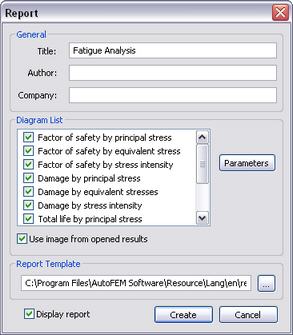
The user can create independent of the AutoFEM Analysis electronic documents which include the main information about the solved problem. The report is created in the html- format.
To create a report, the user needs to:
1.Invoke the dialog for customizing a report with the help of the command of the main menu: AutoFEM | Create Report...;
2.Fill in the fields in the group "General";
3.Check the results, which have to be included in the report, in the "Diagram List";
4.Turn on the options "Use image from opened results" and "Display report";
5.Pressing the button leads to appearance of the dialog for saving the report file.
Congratulations!
You successfully completed the fatigue analysis for the part with the help of the AutoFEM Analysis Lite package.